-
-
学生向け無料ソフトウェアにアクセス
Ansysは次世代の技術者を支援します
学生は、世界クラスのシミュレーションソフトウェアに無料でアクセスできます。
-
今すぐAnsysに接続!
未来をデザインする
Ansysに接続して、シミュレーションが次のブレークスルーにどのように貢献できるかを確認してください。
国および地域
無料トライアル
製品およびサービス
リソースとトレーニング
当社について
Back
製品およびサービス
ANSYS BLOG
December 7, 2022
Embroidery Techniques Improve Carbon Fiber Composites
Although carbon fiber reinforcement technology has been around since the 1960s, the ability to control the orientation of the fibers to optimize material strength properties is a more recent development. Typically, carbon fibers are distributed randomly in a mold, producing strength properties that are isotropic — the same in all directions. But, in some cases, it might be beneficial to combine maximum strength in one portion of a component with flexibility in another portion. This requires careful orientation of the fibers in desired directions in various portions of the component, which can be a challenge.
Recently, BIONTEC of St. Gallen, Switzerland, has returned to the region’s historical roots as the embroidery capital of the world to solve this challenge. At the beginning of the 1900s, more than 50% of the world’s embroidery production came from St. Gallen. Now, with the help of Ansys Composite PrepPost (ACP) software, BIONTEC has adopted the tailored fiber placement (TFP) process to automatically embroider carbon fibers onto a carrier cloth in optimal orientations for efficient and consistent preform creation. These embroidered preforms can then be infused with resin and cured using a resin transfer molding (RTM) process for high-volume manufacturing of carbon composites.
Producing optimized carbon reinforced composites at scale will have tremendous benefits, especially for the automotive and aircraft industries, which must continuously reduce the emissions of their products to become eco-friendly. Lightweight, high-strength fiber composite materials play an important role in reducing fuel consumption and, thereby, emissions.
Simulation of Preform Layers
OST-IWK, in collaboration with BIONTEC, has developed a new simulation framework based on customization of ACP to direct the stitching and forming of the TFP process. The simulation workflow consists of two steps: “study” and “processing.”
In the first step, the main stresses of an isotropic simulation are evaluated to establish the optimal fiber directions for the layer structure, which are then used during the TFP process (a biomimetic design approach). In the second step, the creation of the layered structure in ACP is based on selection rules, lookup tables, and field definitions; then, a customization of the fabric draping function within ACP recreates the completed embroidery path of the TFP process in the model.
Initially, ACP models a laminate layer as homogeneous, with all fibers pointing in one direction. The coordinates of the fiber and matrix areas as specified by the selection rules are then imported into lookup tables by means of scripting. Through the field definition function, the selected information (in this case, material information) overwrites the predefined homogeneous information to modify the direction of the fibers. In this way, the fiber geometry is automatically mapped as precisely as possible. The placement, reshaping, and draping effects are taken into account as realistically as possible. The modeled layer structure can then be benchmarked and validated against customer requirements within the Ansys simulation environment.
Sewing the Preform Layers
The embroidery technique can be used to produce monolithic or sandwich-structured components. Inlays can be used for hollow components, which can be removed after the manufacturing process.
The TFP layers are designed on top of each other. The path of the fibers, as specified by the ACP simulations, is imported into the embroidery machine. Through the movement of the needle of the machine, the fiber geometry of the component is attached with a zigzag stitch to an embroidery background.
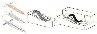
A schematic of the embroidery process at BIONTEC, where a needle is used to punch the roving fiber through the substrate.
Preforming can be greatly simplified by merging several layers of fiber into one stitched layup. For more intricate pieces, many layups are pieced together into a three-dimensional stable preform, much like a puzzle. This highly automated technique, which resembles embroidery, reduces costs and eliminates common faults like gaps, fiber misalignment, wrinkles, and so on.
Resin transfer molding (RTM) is then used to mold the component net shape, reducing machining time. Short cycle times can be achieved without the use of high-pressure RTM systems thanks to infusion-optimized preforms and multicavity tooling, making them less prone to process-induced errors. During RTM, the dry preform is impregnated by the matrix (i.e., the resin-hardener mixture). The RTM tool consists of two mold halves that have the outer contour of the finished component. The reaction resin, also called the matrix, holds the fibers in position, transfers the tension between the individual fibers, and protects the fibers from external influences.
This whole manufacturing chain makes the most of the material’s qualities while also allowing for a great deal of design freedom in the molded composite parts. TFP enables the targeted laying of fiber material to design the component in accordance with the flow of forces by inserting fibers aligned to the load route within the component’s net shape. This allows for better exploitation of the anisotropic properties of the fibers while generating less waste and reducing costs.
TFP Construction of a Bicycle Brake Lever
As a test example, BIONTEC and OST produced a carbon fiber reinforced brake lever for bicycles using the TFP process. The brake lever is made of several layers. To simplify the construction, the material thickening at the end of the brake lever and near the threaded hole were not taken into account. The knitting path is drawn as colored lines over the preform. The fiber geometry is attached to a 0.08-millimeter-thin glass fiber fabric with a zigzag stitch and a fastening thread made of polyester material.
The preform from the brake lever consists of a flat shelf that is cut and then preformed. The fiberglass embroidery background and the polyester embroidery thread are neglected both in the model construction and the simulation because the thread portion is minimal. However, the undulation of the fibers is taken into account through an undulation reduction factor of 5% in the calculation of the modulus of elasticity in the direction of the fibers.
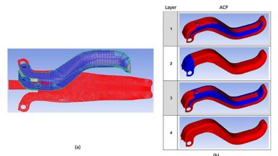
A customized Ansys Composite PrePost (ACP) version is used to bring the information of each stitched layer inside Ansys software (a). Different layers in the preform are then mapped into the model in the correct order (b). Within ACP, the fibers and matrix can be distinguished from one another on the basis of the material specifications.
Two semi-empirical approaches are used here to determine the mechanical properties to be used in the finite element models, along with Material Designer in Ansys Workbench, which makes it possible to calculate homogenized material properties of composite materials given the available original material properties. The two mixing-rule approaches and the calculation using Material Designer show similar results with a fiber volume content of 35%. The simulations are then performed quasi-statically for different load cases (two quality tests by BIONTEC) and validated based on measurements and optical validations.
In this work, the focus is on the rigidity of the component, which is to be simulated with ACP. The rigidity of the simulation is calculated from the force (50 N) and the vertical-right displacement of the remote point. In the first load case, the brake lever is loaded in the direction of actuation: The brake lever is positioned at an inclination of 24° to the clamping point and loaded vertically downwards at the end of the lever. The second load case corresponds to a shear load, where the brake lever is set up horizontally and has an angle of 24° to the clamping point and an additional angle of 30° to the ground.
To validate the simulation, the measurements focus on the linear range. In the cases considered, the averaged measured experimental stiffnesses are within 8% of the values obtained from the finite element model. The experimental dispersion in measured stiffness values was between 15% and 21%. During the tests, the displacements and expansions are tracked using a GOM 3D camera. All the simulation data sets deviate only slightly from the measurement data. With the material properties homogenized by Material Designer, the simulation shows good prediction ability in terms of mechanical properties.
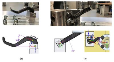
Vertical downwards load case (a) and shear load case (b) on a brake lever.
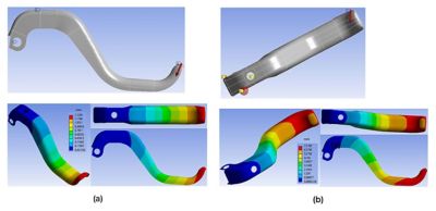
Predicted deformation on a brake lever for the vertical downwards load case (a) and the shear load case (b).
The customized ACP workflows, along with the other modeling tools of the Ansys composites ecosystem, have demonstrated the ability of the software to capture the complex microstructural details and the underlying behavior of 3D composites made through novel TFP manufacturing techniques capable of placing continuous tows or rovings of fibers in any direction. A closer integration between modeling software and the software driving the actual fiber-reinforced plastic (FRP) manufacturing process is likely to unlock powerful as-manufactured optimization studies. These studies will yield optimal topology and fiber alignment, resulting in the best composite solution for specific applications.