-
-
学生向け無料ソフトウェアにアクセス
Ansysは次世代の技術者を支援します
学生は、世界クラスのシミュレーションソフトウェアに無料でアクセスできます。
-
今すぐAnsysに接続!
未来をデザインする
Ansysに接続して、シミュレーションが次のブレークスルーにどのように貢献できるかを確認してください。
国および地域
無料トライアル
製品およびサービス
リソースとトレーニング
当社について
Back
製品およびサービス
ANSYS BLOG
March 30, 2023
Parametric Design Changes Entirely Within Ansys Fluent
Analysts and engineers have run computational fluid dynamics (CFD) simulations using Ansys Fluent for decades. Additionally, the concept of setting up and running a parametric Fluent model is not new. However, additional tools were typically needed to drive the parametric CFD model. Now, a fully parametric model can be set up, run, and post-processed entirely within a single window. This Fluent Parametric Workflow enables users to streamline robust workflows, perform trade studies, support quality by design (QbD) initiatives, and more all in one place.

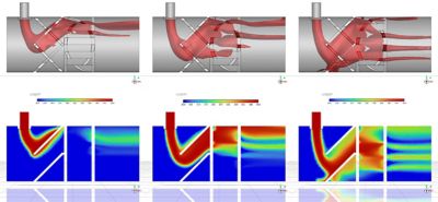
Figure 1. Temperature distribution within a static mixer parametrically studied as a function of side inlet mass flow change. Isosurface based on average temperature (top), temperature contours (bottom).
The advantages and capabilities of the Fluent Parametric Workflow, which don’t require additional tools or scripting, are:
- Different methods to create input and output parameters (i.e., through named expressions instead of user defined functions, or UDFs).
- User-friendly ways to record and replay commands and case modifications.
- Advanced report generation/recording that creates standalone reports in PDF and interactive HTML formats.
- Single-design or multiple-design point reports (i.e., a design of experiments, or DOE) to enable side-by-side design point comparison.
- The ability to integrate with the new mesh morphing capability that enables geometrical changes within the Fluent interface without having to revisit CAD.
- Ansys DesignXplorer and Ansys optiSLang integrations for automated DOE creation.
- The ability to run design points concurrently for manageable turnaround times compared to the conventional sequential design point update.
Interpreting the massive amounts of data that the DOE provides typically involved reading the DOE results in yet another optimization-centric tool. Investigations such as relationships between output and input parameters, sensitivity of the output parameters with respect to each input parameter, and how well a response surface (or a metamodel) represents the design space are now possible and can be read with one click in optiSLang for detailed post-processing. This includes the creation of a functional mockup unit (FMU), which is the building block for system-level modeling.

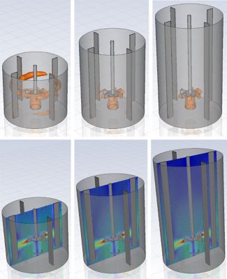
Figure2. Studying the effect of liquid level change within a mixing tank through mesh morphing combined with Fluent Parametric Workflow. Gas concentration (top), velocity contours (bottom).
In summary, the new Fluent Parametric Workflow opens the door for:
- Exploring the design space with advanced reporting capabilities without reverting to CAD.
- Running large simulations using large clusters while running design points either sequentially or concurrently depending on hardware availability and turnaround time requirements.
- Making the most use of the simulation DOE and using it as the building block for:
- Optimization when using optiSLang, with minimal learning curves.
- Creating a reduced-order model (ROM), metamodel, or FMU to be used alone or within a system model that can even be promoted to a digital twin.
- Accelerating innovation by minimizing non-value-added and repetitive tasks, and fully automating the CFD simulation workflows that are enabled by parametric variations for more product design options.
Additional Resource
Ansys Learning Hub (ALH) mixing page: “Simulation of steady vortex in a stirred tank using Ansys Fluent Parametric Workflow"