Synopsys and Ansys power the future of innovation—connecting silicon to systems.
-
-
学生向け無料ソフトウェアにアクセス
Ansysは次世代の技術者を支援します
学生は、世界クラスのシミュレーションソフトウェアに無料でアクセスできます。
-
今すぐAnsysに接続!
未来をデザインする
Ansysに接続して、シミュレーションが次のブレークスルーにどのように貢献できるかを確認してください。
無料トライアル
製品およびサービス
リソースとトレーニング
当社について
Back
製品およびサービス
ANSYS BLOG
November 7, 2018
How to Convert a Calcination Kiln to Use Pure Natural Gas without Trial-and-Error
There are a lot of advantages to using natural gas to fuel your calcination kiln and heating systems.
First, it’s typically cheaper than other energy sources, like heavy fuel oil (HFO). Natural gas is also supplied via pipelines, so you don’t have to spend money storing it.
The problem is, you can’t just connect natural gas burners to your process and immediately expect the same results from the old liquid fuel burners.
This is because natural gas has a higher flue gas volume and ignition temperature. It also has a lower heat transfer rate compared to most liquid and solid fuels.
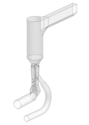
3D model of an in-line calciner (ILC)
Many plants might attempt to optimize the new fuel and burner system using trial-and-error. However, this can be risky and waste a considerable amount of time, money and fuel.
Instead, FCT Combustion suggests you use simulation to model your calciner, its burner designs, burner placements and mixing to optimize the system to use natural gas.
In fact, in one study, FCT helped a client save four percent of their fuel usage and increase their feed rate by 15 percent. FCT’s client saved $570k to $680k (€500k to €600k) a year thanks to the simulation-based redesigns.
How to Model a Kiln Using Ansys Fluent CFD Software
When you convert a calciner from HFO to natural gas there are a lot of factors to consider.
“First, you need to understand the inherent differences between the fuels — like how they disperse, mix and burn. You also need to understand the aerodynamics of the calciner vessel, the location of the feed and the resultant heat transfers. Then, you can estimate the degree of calcination,” says Yvonne Yu, computational fluid dynamics (CFD) modelling engineer at FCT Combustion.
To better understand these factors, FCT modeled their client’s kiln using Ansys Fluent. These simulations use about 2.6 million cells and a standard k-ε model to simulate turbulence.
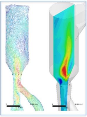
Computational fluid dynamics and thermal simulations for a calciner running on 100 percent natural gas.
“The discrete phase model was employed to simulate the HFO droplets and the feed particles,” explains Yu. “For the reactions, a one-step mechanism is used to model oil vapor oxidation and a two-step mechanism is used to model natural gas reactions.
“A discrete ordinate thermal radiation model is also applied to model the heat transfer,” adds Yu. “This model accounts for gaseous radiation, uses a weighted-sum-of-gray-gases model — which assumes a constant absorption coefficient in the gas, hence gray gas — and accounts for radiation exchange from and between the walls.”
FCT models the calcination of the calcium carbonate feed using an endothermic particle surface reaction. The process converts the reactants into calcium oxide and carbon dioxide.
Finally, FCT uses point source air-blast atomizers that have a cooling air annulus surrounding them to model the oil burners. This differs from the natural gas burners in that they have swirled holes that inject the air and axial holes to inject the gas.
Simulations Help Optimize a Kiln to Run on Natural Gas
The FCT model simulated three different fuel mixes in the calciner: pure HFO, pure natural gas and an 80/20 mix of natural gas and HFO.
The simulation shows that as the proportion of natural gas increases in the fuel, more carbon monoxide is produced in the kiln. Obviously, this is not acceptable for safety and fuel efficiency reasons.
Additionally, the simulation shows how adding natural gas to the mix changes the kiln’s flow pattern and its ability to calcine the feed material.
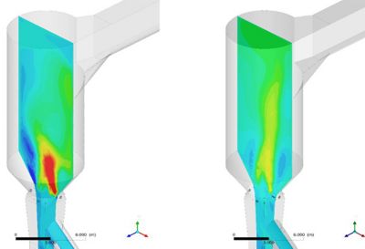
Simulations help FCT optimize the placement and design of the burners in the calciner for use with natural gas.
To improve these results, FCT modifies the burner designs and locations within the calciner and runs the simulations again. In the case of this particular calciner, FCT found that placing a burner at the exit of the tertiary air duct improves performance considerably.
In fact, FCT’s clients note that their kiln performs better now that it runs on natural gas than when it ran on HFO.
To help convert your process to run on natural gas, try simulating it using Ansys Fluent.
FCT Combustion is supported by LEAP Australia, Ansys Channel Partner for Australia and New Zealand.