Synopsys and Ansys power the future of innovation—connecting silicon to systems.
-
-
学生向け無料ソフトウェアにアクセス
Ansysは次世代の技術者を支援します
学生は、世界クラスのシミュレーションソフトウェアに無料でアクセスできます。
-
今すぐAnsysに接続!
未来をデザインする
Ansysに接続して、シミュレーションが次のブレークスルーにどのように貢献できるかを確認してください。
無料トライアル
製品およびサービス
リソースとトレーニング
当社について
Back
製品およびサービス
ANSYS BLOG
February 26, 2019
Designing for Additive Manufacturing Ensures Parts Meet Tolerances
Meeting tolerances has always been a challenge for subtractive and additive manufacturing.
If manufacturers can’t produce parts that fall within specified size limits, for example, they won’t be able to fill orders to the customer’s satisfaction.
Tolerances have gotten increasingly tighter in recent decades as components, like semiconductors and printed circuit boards, shrink
Simulation helps manufacturers ensure parts built using additive
manufacturing will meet tolerances.
Additionally, a more precise fit within an assembly is required to increase the performance of products with moving parts.
Manufacturers have continuously adapted their machining techniques to meet these tolerances in traditional manufacturing processes. In subtractive manufacturing, machinists start with a block of material and precisely cut away at it until they achieve the final, desired shape.
It’s like the old joke about how Michelangelo sculpted the magnificent form of his masterpiece David. He simply chiseled away anything that didn’t look like David. Of course, if sculpting was that easy, we’d all be master sculptors.
The increasing popularity of additive manufacturing (AM) — starting with nothing and building parts layers by layer — has created new opportunities while also introducing new tolerance challenges. Simulation can overcome these challenges.
Tolerancing is a Major Challenge in Additive Manufacturing
Parts deform as they print, especially in powder-bed metal AM.
Consider the AM process: The machine lays down a layer of metal powder on a substrate according to a designed pattern.
A laser heats the powder particles until they melt. When the meltpool cools, it shrinks and forms a solid structure.
The AM machine then deposits a second layer of metal powder atop the first.
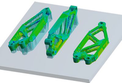
Additive manufactured parts deform due
to varying
degrees of thermal expansion.
The laser then melts the second layer of powder particles, but in the process, it also heats up the first layer. As the layers bond together, stresses build up due to varying degrees of thermal expansion in the layers.
Deformation makes it extremely hard to meet tight tolerances. As a result, many parts are scrapped. In a worst-case scenario, a deformed part can interfere with the movement of the AM machine, leading to a failed build and damaged equipment.
Additive Manufacturing Simulation to the Rescue
Ansys has developed simulation solutions that give manufacturers confidence that parts will meet all design specifications without damaging the AM machine.
Design for additive manufacturing (DfAM) doesn’t eliminate deformation due to thermal and mechanical stresses as the part is built — it simply takes the deformation into account and builds it into the original design.
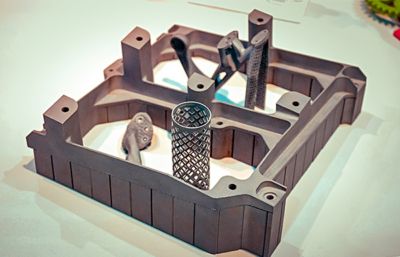
Manufacturers can import CAD files into Additive Print to
help them design for additive manufacturing.
It’s like a golfer who knows he always slices his drive off the tee, causing it to land in the right-hand rough. So, he aims a little left off the tee to compensate for the distortion to the desired flight path of the golf ball. Now, it lands in the middle of the fairway.
The Ansys Advantage article Ensuring Additive Manufacturing Success discusses how Ansys has incorporated DfAM into Ansys Additive Print to help engineers achieve first-build success.
Additive Print lets manufacturers see a simulation of an AM print before it is performed using actual metal powders and lasers. After importing their CAD or STL files into Additive Print, manufacturers can visualize what will happen to their designs during the printing process. They can then adjust the design accordingly.
A Design for Additive Manufacturing Case Study
In the Ansys Advantage article Getting Metal 3D Printing Right the First Time with Ansys Additive Print, engineers from PADT, Inc., an Ansys Channel Partner, describe how they used simulation to alter the design of a part they had been making for decades using standard manufacturing techniques.
While PADT engineers have been using AM for plastics for the last 25 years, they started working with metal-based AM only a year ago.
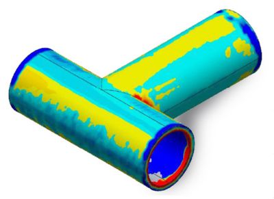
T-tube simulations in Additive Print helped PADT engineers meet tolerances when building the part with additive manufacturing.
During their experimentation with laser powder-bed AM techniques, they have experienced variable success. Some metal parts are close to tolerance, while others “curl up like potato chips.”
To gain a better understanding of metal-based AM, PADT engineers turned to a T-tube part that they’d used for decades.
By simulating this well-understood part in Additive Print, they learned of some modifications they would have to make to the T-tube design so it would meet customer tolerances when manufactured using AM.
Ansys’ AM simulation solutions take the guesswork out of metal AM while reducing costs due to discarded parts and lost raw materials. To learn more, read the AM-focused issue of Ansys Advantage.