Synopsys and Ansys power the future of innovation—connecting silicon to systems.
-
-
学生向け無料ソフトウェアにアクセス
Ansysは次世代の技術者を支援します
学生は、世界クラスのシミュレーションソフトウェアに無料でアクセスできます。
-
今すぐAnsysに接続!
未来をデザインする
Ansysに接続して、シミュレーションが次のブレークスルーにどのように貢献できるかを確認してください。
無料トライアル
製品およびサービス
リソースとトレーニング
当社について
Back
製品およびサービス
ANSYS BLOG
September 25, 2020
Simulate Automotive Radar in 5 Dimensions
Automotive radar has emerged as one of the backbone technologies in the automotive industry’s advanced driver assistance systems (ADAS) revolution. Because radar uses electromagnetic waves to sense the environment, it can operate over a long distance in poor visibility or inclement weather conditions. Designing automotive radar that accurately captures diverse traffic situations will be essential in making autonomous operations safe.
In the past, automotive radar was used in vehicles for basic operations such as automatic emergency braking (AEB) and adaptive cruise control (ACC), where the radar sensor only had to provide the vehicle with information relating to the distance and speed of the target in front of it.
However, recent trends accelerated by the race to deploy a fully autonomous vehicle have increased the amount of information that an autonomous vehicle demands from the radar sensor. Specifically, after detecting a target, the host vehicle will need to answer the following questions:
- How far is the target from me?
- How fast is the target approaching or departing?
- Is the target to my left, right or straight ahead?
- Is the target on the road or above the ground?
- What is this target? Is it a pedestrian or vehicle, for example.
Automotive radar technology helps the vehicle and its onboard perception algorithms answer these questions by providing the following “five-dimensional” datasets:
- Range
- Doppler
- Azimuthal direction of arrival (DoA)
- Elevation direction of arrival (DoA)
- Micro-Doppler
As vehicles migrate from level 1 to level 5 full autonomy, automotive radar technology will be used for far more than emergency breaking and adaptive cruise control with ever-increasing reliability and accuracy demands.
While building and testing is extremely valuable, if used by itself, it can be prohibitively expensive and time-consuming simulation of radar sensor hardware performance is a cost-effective and efficient approach for designing radar sensors. Using simulation, engineers can confidently design, test and validate sensors in a much shorter product development cycle.
Using Simulation to Validate Automotive Radar Systems
While hardware simulation is valuable during the sensor design stage, simulation becomes even more valuable when validating and testing radar sensor performance in the real world. Specifically, radar engineers need to be sure that the radar sensors will accurately sense the environment and provide consistent information to the vehicle’s perception algorithms. Failure to do this can severely compromise the safety of fully autonomous vehicles.
Furthermore, engineers will need to test the performance of a radar sensor in the so-called corner cases that may prove too dangerous or costly for physical testing. In fact, it has been estimated that 8.8 billion driving miles will need to be completed before fully autonomous vehicles reach customers. Simulation, therefore, has emerged as the only practical way of reaching this goal. Using simulation, engineers can complete billions of virtual drive miles while also safely testing automotive radar sensor performance in corner cases.

Fig. 1: Full-scale traffic scene for high-fidelity electromagnetic simulations using Ansys HFSS SBR+ solver
However, not all radar sensor simulations in virtual drives are created equal; they can vary widely in accuracy and speed because of the level of electromagnetic fidelity introduced into the simulations.
Specifically, the accuracy of automotive radar simulations depends on how realistic the virtual environment is and how many electromagnetic wave propagation phenomena are included. To speed up the radar simulations, engineers sometimes use simple primitives to define typical actors in traffic scenes. An example of this is using a box to define a car or a group of ellipsoids to define a pedestrian. Another technique is to use system-level simulations that define targets as pre-defined radar cross section values that do not require active electromagnetics simulations.
Each of these approaches reduce the fidelity of the synthetic radar returns that are obtained from these virtual radar sensors during driving simulations. Failure to capture the true electromagnetic response of a traffic scene can lead to premature validation of a sensor that will behave differently and unpredictably in real life. Furthermore, it can nullify the gains introduced by artificial intelligence (AI) algorithms that would have been built with incorrect synthetic radar data.
Ansys HFFS SBR+ solver is an asymptotic, ray tracing electromagnetic solver that efficiently solves electrically large problems. HFSS SBR+ uses geometric optics (GO), physical optics (PO), uniform theory of diffraction (UTD), physical theory of diffraction (PTD) and creeping waves (CW) to accurately predict the propagation of electromagnetic waves.
We’ll demonstrate how engineers can obtain highly accurate synthetic radar returns from full-scale traffic scenes using HFSS SBR+. Specifically, we will show how range-Doppler maps, range-angle maps and micro-Doppler profiles can be obtained by post-processing HFSS SBR+ synthetic radar returns.
Dimension 1 and 2: Range and Doppler
On a fundamental level, radar sensors determine the range of a target by sending out an electromagnetic wave and listening for the reflected signal. The time delay between transmission and reception of the reflected signal can be used to calculate the range of the target.
To determine the velocity of the target, radar exploits the Doppler effect by measuring the change in the frequency of the reflected signal. However, to do this, the radar sensor needs to emit multiple pulses in a coherent processing interval (CPI) to determine the frequency change. This presents a challenge for electromagnetic simulations because a CPI can mandate hundreds of simulations to obtain a single range-Doppler frame.
HFSS SBR+ addresses this challenge using its advanced Doppler processing (ADP) feature. Using ADP, HFSS SBR+ obtains the synthetic radar returns for an entire range-Doppler frame in the same time it takes to emit a single pulse. This results in an acceleration of over 100X for some radar scenes.
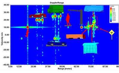
Fig. 2: Range-Doppler map of the scene shown in Fig. 1, obtained using HFSS SBR+’s advanced doppler processing (ADP) feature.
Dimension 3 and 4: Azimuth and Elevation Direction of Arrival (DoA)
Automotive radar sensors can determine the direction of arrival of a target by using multiple transmitter (Tx)/receiver (Rx) antennas that are physically separated. Because the spacing between the antennas is already known, the direction of arrival can be determined by measuring the progressive phase shift between the signals received by each of the antennas.
Along with determining the range and velocity of targets with high resolution, autonomous vehicles navigating complex urban environments need radar sensors with high azimuth and elevation resolution.
Size and cost constraints limit the physical number of channels that can be used to achieve high resolution DoA estimation. Multiple-input/multiple-output (MIMO) schemes achieve larger virtual arrays using fewer physical channels than would be needed for a single-input/multiple-output (SIMO) system. Increasing the number of channels significantly increases the simulation overhead because more Tx/Rx coupling needs to be computed. HFSS SBR+ can efficiently handle the simulation of any arbitrary number of MIMO channels. By using simulation, engineers can confidently determine the number of channels needed to meet performance specifications for various driving scenarios before they even build the sensor.
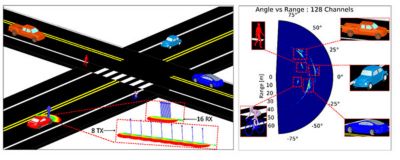
Fig. 3: Full-scale traffic scene and its azimuthal range-angle map obtained using a 128 channel MIMO sensor. The same principle can be used for elevation DoA.
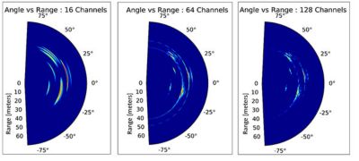
Fig. 4: Evaluating the impact of the number of channels on the DoA estimation resolution. Increasing the number of channels improves the resolution.
Dimension 5: Micro-Doppler
We mentioned how the relative motion between a vehicle where a radar sensor is mounted and a target in the environment changes the frequency of the reflected signal. This is the Doppler effect. The velocity component is typically the bulk motion of an entire platform. If the target has additional components on it that possess rotational or oscillatory motion, these additional components can introduce so-called micro-motions that can further modulate the reflected signal. This further modulation of the reflected signal is called micro-Doppler.
For example, a human target has bulk motion velocity that can be attributed to the torso. The legs, feet and arms introduce their own oscillatory micro-motions that lead to a unique micro-Doppler signature. Specifically, using micro-Doppler, vehicles can determine if a target is a pedestrian, cyclist or another vehicle. Micro-Doppler can even be used to distinguish whether a target is an animal or human. The high-fidelity physics approach of HFSS SBR+ enables engineers to accurately simulate the distributed nature of targets and the micro-motion induced micro-Doppler effect.
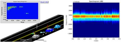
Fig.5: Traffic scene (left) and spectrogram (right) of a “gliding” pedestrian without swinging limbs.
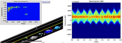
Fig.6: Traffic scene (left) and spectrogram (right) of naturally walking pedestrian with swinging arms and legs. The micro-Doppler introduced by the arms and legs modulates the Doppler returns from the bulk platform (torso).
Automotive Radar Systems Advance Fully Autonomous Vehicles
Automotive radar is the backbone sensor technology essential in developing fully autonomous vehicles. Radar sensors will be used not only to detect targets, but to accurately determine how far the target is, at what speed and angle it is moving, and even whether the target is an animal, a pedestrian or a cyclist.
HFSS SBR+ is a physics-based electromagnetic solver that enables engineers to accurately simulate real-world traffic conditions and develop radar sensors for safe autonomous vehicle operation.