-
-
Access Free Student Software
Ansys empowers the next generation of engineers
Students get free access to world-class simulation software.
-
Connect with Ansys Now!
Design your future
Connect with Ansys to explore how simulation can power your next breakthrough.
Countries & Regions
Free Trials
Products & Services
Learn
About
Back
Products & Services
Back
Learn
Ansys empowers the next generation of engineers
Students get free access to world-class simulation software.
Back
About
Design your future
Connect with Ansys to explore how simulation can power your next breakthrough.
Free Trials
ANSYS BLOG
April 20, 2022
The Latest Software Updates for Electronics Reliability Simulations
In Ansys 2022 R1, our developers made a number of software updates to the Electronics Reliability product portfolio, which includes Ansys Sherlock, Mechanical, LS-DYNA, and Icepak. Ansys Electronics Reliability solutions enable you to understand and optimize the reliability of your electronic devices at the component, board, and system-levels.
Some of the biggest updates include increased file type support and integrations between products; enhanced workflows for reinforcement element studies; additional support for scripting, automation, and design exploration; and improvements to our core element technologies.
Let’s look at the latest updates in 2022 R1, how to download the latest versions of our software, and how these updates will help improve your simulation analyses.
Ansys 2022 R1 Updates
Perform Advanced Thermo-Mechanical Analyses
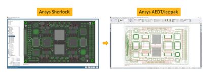
An exciting capability in this release is the ability for Sherlock users to export printed circuit board (PCB) models into Icepak using an Exchange database (EDB) file format. This connection allows you to perform advanced thermal simulations in Icepak to understand temperature effects on your components, boards, and enclosures. You can also bring thermal map results from Icepak back into Sherlock for solder fatigue time-to-failure (TTF) predictions by importing images of results. This opens up the ability for more advanced analyses and greater understanding of failure risks driven by thermal events.

Figure 1. In Ansys 2022 R1, users can export PCB models from Sherlock into Icepak for advanced thermal analysis simulations.
Evaluate Trade-Offs With Part Location Reliability Studies
In 2022 R1, our new part location application programming interfaces (APIs) can help you rapidly evaluate trade-offs associated with moving components on a board under a variety of loading conditions. These new APIs allows you to set a part’s location property and determine a list of valid part location units and board side values.
In the figure below, you can see how easy it is to determine what will happen to a component’s reliability (as it relates to mechanical shock) as a component is moved around the board. By moving the component left, the component is not meeting the desired goal of 20% probability of failure after 10 years. Moving the component to the right is the better option and meets the desired reliability goal.

Figure 2. Parts location APIs help users rapidly identify reliability risks based on component placement.
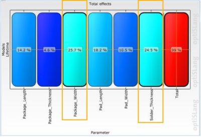
Additionally, there is an exciting new connection between Sherlock and Ansys optiSLang that uses the aforementioned APIs so you can study the effects of parameterizing key variables, such as part properties, component locations, and stack up information influence on key outputs like TTF. These scripts can be incorporated into sensitivity studies and optimization routines in optiSLang.

Figure 3. Sample sensitivity study results in Ansys optiSLang.
In the figure above, you can see that the study has shown that the package width and solder thickness values have the greatest impacts on product lifetime. The combination of Sherlock and optiSLang can provide you with a better understanding of the trade-offs associated with various design decisions on your PCB reliability. Understanding what impacts TTF the greatest can inform design decisions and improve overall product life.
Take Advantage of Time-Saving Automations
Another focus for our electronics reliability software updates in 2022 R1 is providing you with time-saving workflows. New in this release is a semi-automated reinforcement element workflow that enables you to automate setups in Ansys Workbench and Ansys Mechanical when using Sherlock as a pre-processor.
For this use case, you can start in Ansys Sherlock to create a PCB model and then use the new Export Trace Reinforcement Model option to export to Workbench. Selecting this option enables you to automatically export PCB information (component information) and board information (stackup properties, etc.) along with trace and via geometries (reinforcements). This process automatically handles several steps that were previously manual, including setting up reinforcement materials, thicknesses and cross-sections, and other model inputs. Once the export and setup process has been completed, users will typically only need to apply their desired mesh settings and physics set up (loads and boundary conditions) before running an analysis.

Figure 4. The new semi-automated trace reinforcement workflow eliminates extra steps so users can export trace reinforcement models to Ansys Workbench in one block.
Additionally, APIs available in Sherlock automate and streamline existing workflows, enabling users to:
- Run simulations in several languages, including Python.
- Run simulations in batch mode.
- Automatically open existing projects, import ECAD files, update parts from the parts library, query and modify stack ups and more.
- Explore the influence of key design variables on component TTF and other critical metrics.
- Get and set component location information (new in 2022 R1).
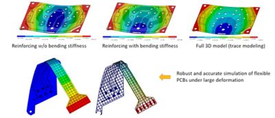
Finally, for flexible circuit board (FCB) applications (often used in consumer electronics like wearables and smartphones, among other industries), there is a new bending stiffness property for the smeared reinforcement approach that greatly improves simulation accuracy and efficiency when analyzing FCB and other models.

Figure 5. The new bending stiffness capability provides improved accuracy for 3D smeared reinforcing models.
Further, the popular Trace Mapping feature in Mechanical has been enhanced to include support for solid-shell elements (in addition to existing support for solid and shell elements). Using solid-shell elements is often preferred when working with larger PCBs, as you can create meshes with fewer elements through thickness (reduced mesh count) while retaining a high degree of accuracy in simulations.
Access the Latest Version of the Software
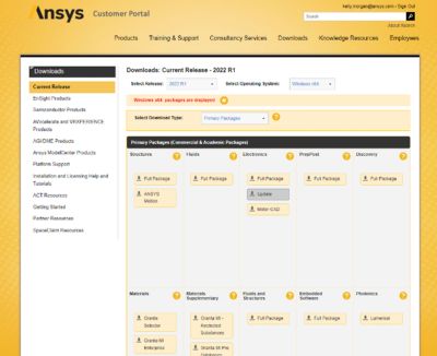
You can download the latest versions of all Electronics Reliability product software (Sherlock, Mechanical, LS-DYNA, and Icepak) at the Ansys Customer Portal (registration required).
Ansys Sherlock, Mechanical, and LS-DYNA are included in the Structures package, while Ansys Icepak can be accessed by first installing the Fluids and Electronics packages.

Figure 6. Download page on the Ansys Customer Portal
Where can I Learn More?
If you are a current customer and are interested in learning more about our electronics reliability workflows, you can access our new Electronics Reliability page on the Ansys Learning Hub. Here, you can access video tutorials, walkthrough guides, training resources, and our full list of on-demand webinars.
If you are not a current customer, but interested in learning more about our products, you can: