Synopsys and Ansys power the future of innovation—connecting silicon to systems.
-
-
Access Free Student Software
Ansys empowers the next generation of engineers
Students get free access to world-class simulation software.
-
Connect with Ansys Now!
Design your future
Connect with Ansys to explore how simulation can power your next breakthrough.
Free Trials
Products & Services
Learn
About
Back
Products & Services
Back
Learn
Ansys empowers the next generation of engineers
Students get free access to world-class simulation software.
Back
About
Design your future
Connect with Ansys to explore how simulation can power your next breakthrough.
Free Trials
ANSYS BLOG
November 27, 2018
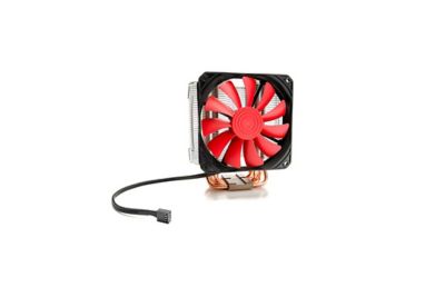
How to Keep Electronic Components Cool with CFD and Thermal Network Modeling
Every year, our electronic components are becoming more complex. This means engineers need to include more details into their computational fluid dynamics (CFD) simulations to ensure their final products don’t overheat.
However, many engineering teams find it infeasible to include this level of detail into large 3D CFD simulations. These teams don’t always have access to high-performance computing (HPC) resources powerful enough to solve their simulations in a reasonable time.
To address this dilemma, Ansys Icepak offers users access to thermal networks.
A thermal network can represent an electronic component in a 3D CFD simulation with a 1D model. The thermal network communicates directly with the 3D CFD domain in which it is embedded.
The thermal network characterizes the heat performance of a component, allowing engineers to understand how it and the larger system will react to the current conditions. The 1D nature of the thermal network reduces the overall size of the simulation, so engineers can quickly simulate and optimize their designs.
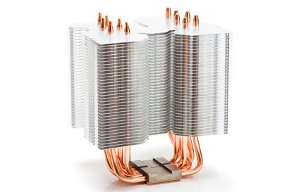
Thermal simulations of electrical components are becoming more complex. Engineers need to simplify these simulations if they are going to ensure the final product stays cool.
Thermal networks are lumped-parameter simplifications of complex thermal systems. Thermal networks can represent various components, including:
- Integrated circuits (IC).
- External heat exchangers.
- Liquid loop cold plates.
- Heat pipes.
And more.
Even the effects of heat flowing through wires and solder balls can be incorporated into a thermal network.
If you are acquainted with Ohm’s law of electrical resistance, you’ll find thermal networks and the concept of thermal resistance comes naturally.
Ohm’s law can simplify an component’s electrical resistance into a 1D formula. Similarly, thermal networks do the same for the thermal resistance of components.
So, just as you can build an electrical circuit, you can also build a thermal circuit — or network. Icepak integrates the thermal network into a 3D CFD simulation.
This way engineers can model, simulate and optimize more complex electronics without creating detailed representations of every component within a 3D mesh. Instead, these components are replaced with 1D stand-ins that reduce the mesh, computational time and simulation complexity.
Another benefit to thermal networks is that they protect intellectual property (IP). Since the networks are 1D models, they obfuscate the 3D designs they represent. As a result, they can be shared with customers without risking IP.
To learn of other ways to reduce a thermal model, read the Ansys Advantage article, Hot Flash.
Engineers can simplify the CFD simulation of electronic components using thermal networks.