-
-
Access Free Student Software
Ansys empowers the next generation of engineers
Students get free access to world-class simulation software.
-
Connect with Ansys Now!
Design your future
Connect with Ansys to explore how simulation can power your next breakthrough.
Countries & Regions
Free Trials
Products & Services
Learn
About
Back
Products & Services
Back
Learn
Ansys empowers the next generation of engineers
Students get free access to world-class simulation software.
Back
About
Design your future
Connect with Ansys to explore how simulation can power your next breakthrough.
Free Trials
ANSYS BLOG
May 10, 2023
From Concept to CubeSat Part 3: Using Ansys Mechanical to Generate Finite Element Analysis Results
In the aerospace industry, CubeSats have emerged as a low-cost, easily manufacturable solution for space-based optical systems. This blog series introduces how Ansys Zemax software can be used to take a CubeSat from an initial optical design to an opto-mechanical package ready for structural-thermal-optical-performance (STOP) analysis.
For an opto-mechanical payload, it is important to consider the structural and thermal impacts that it will experience in-orbit. With Ansys Mechanical, a finite element analysis (FEA) can be performed to analyze these effects. To prepare for FEA, Mechanical can be used to mesh the opto-mechanical model and define boundary conditions for the analysis. Once an FEA is completed, the Export to STAR extension within Mechanical provides a streamlined process for preparing the data for use with the Ansys OpticStudio STAR module.
To learn about the entire workflow, start with Part 1 of this blog series: Using Ansys Zemax to Develop a CubeSat System.
Preparing the Design for FEA
In Part 2 of this blog series, the opto-mechanical design was finalized in PTC Creo using OpticsBuilder. Next, the completed design was exported as a STEP file. Within Mechanical, the STEP file was opened and prepared for FEA. For the purposes of this example, the following material definitions were chosen for the design:
- Both mirrors are built out of a low-CTE aluminum substrate (Al-MS40Si)2.
- The main frame is built from carbon fiber-reinforced polymers.
- The metering rods are built out of invar.
- The image sensor is assumed to be made from printed circuit board (PCB) laminate.
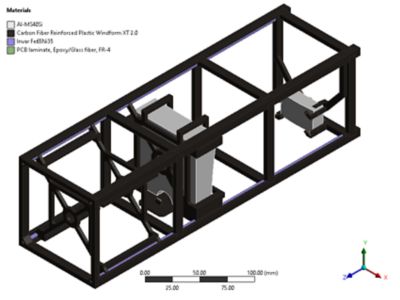
Materials definitions
After assigning materials to the model, it was then meshed. A mesh is made of elements that contain nodes representing the shape of the geometry. For the mesh, it is important to note that the element size was adjusted for both mirror surfaces such that they each contained at least 10,000 nodes. A high number of nodes ensures good fit quality once FEA data is brought into the OpticStudio STAR module for future analysis. The following image shows the final mesh that was used for the opto-mechanical model.
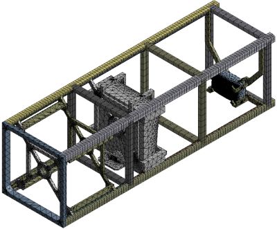
Mesh as defined in Ansys Mechanical
Defining Boundary Conditions
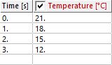
For the purposes of this example, the only load considered was a thermal condition that caused all components to expand according to their thermal coefficient of expansion (CTE). It was assumed the CubeSat’s radiation control system would insulate the optics from large fluctuations in temperature. Discrete temperatures of 12 °C, 15 °C, and 18 °C were chosen to represent the operational temperature range experienced by the CubeSat in low Earth orbit (LEO).
The nominal design as built in OpticStudio was assumed to have been built in an ambient, room temperature environment of 21 °C. This is the reference temperature at which the geometry was defined.
The temperatures as implemented in Mechanical were as follows:
FEA Result
With the opto-mechanical model meshed and the thermal loading determined, an FEA was then conducted within Mechanical. The following image showcases the structural deformation impact for the lowest operational temperature (12 °C).
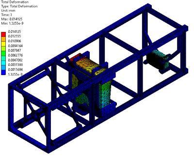
Structural deformation result
Because this payload consists of two mirrors, only structural deformation data was solved for. Solving for thermal index changes throughout an optic would be necessary if any refractive components were integrated into the system. Both structural deformation data and thermal index data can be exported to the OpticStudio STAR Module for analyzing their impact on system-level performance.
With the FEA completed, the next step is to bring the structural deformation data for both mirrors into the OpticStudio STAR Module. With the Mechanical Export to STAR ACT extension, the structural deformation data can be easily exported into the text file format utilized by STAR. To learn more about this extension, read the corresponding Knowledgebase article on the Ansys Zemax website.
For more information about Ansys Mechanical, visit the product page.
For a more in-depth look at this portion of the CubeSat design workflow, read this corresponding Knowledgebase article.