Synopsys and Ansys power the future of innovation—connecting silicon to systems.
-
-
Access Free Student Software
Ansys empowers the next generation of engineers
Students get free access to world-class simulation software.
-
Connect with Ansys Now!
Design your future
Connect with Ansys to explore how simulation can power your next breakthrough.
Free Trials
Products & Services
Learn
About
Back
Products & Services
Back
Learn
Ansys empowers the next generation of engineers
Students get free access to world-class simulation software.
Back
About
Design your future
Connect with Ansys to explore how simulation can power your next breakthrough.
Free Trials
ANSYS BLOG
February 28, 2018
Speed Up CFD Spray Simulations
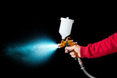
Sprays are everywhere. From fuel injectors in combustion engines to spray nozzles in paint shops and to food industry for material processing, one can see their applications. Sprays can be found in the form of sprinklers on our yards and on the agricultural fields. We use spray nozzles to distribute pesticide and clean our windshields while driving on an unpaved road. With such a variety of applications, there has to be a spectrum of methods and parameters available to the designer of spray equipment to control the spray characteristics including computational fluid dynamics (CFD) spray models.
Physical spray measurement used to be the only way to determine if a certain spray head was designed properly for the given fluid and operating conditions and required droplet sizes. With advancement in computational power and the availability and fidelity of physical models coming out of research work, we now have computational tools that can complement or even, replace the need for laboratory measurements.
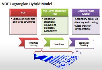
Ansys Fluent has always provided accurate, validated results for any form of sprays but the large computational requirements limited the size of problems that one could solve, especially if the goal was to resolve very fine spray details. With the release of Ansys 19, we are introducing VOF to DPM CFD spray, an exciting new hybrid multiphase model that will make simulation of spray processes with the finest details more computationally practical. As the name suggests, this model uses two primary models which are already well established in Fluent. The Volume of Fluid (VOF) model tracks the liquid-gas interface while the Discrete Phase Model (DPM) is a separate solver that tracks discrete particles suspended in a Eulerian phase. This hybrid model transitions from a full VOF to a DPM solution is shown in the picture below.
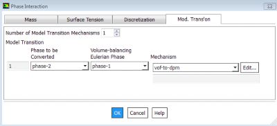
This new model links the two models by moving very small VOF “blobs” to the DPM solver and hence reducing the need to track these small blobs. This allows us to model primary atomization and subsequent breakup, evaporation and reactions in the same setting. How does it work in Fluent? Here are a few screenshots of the GUI.
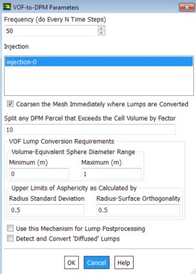
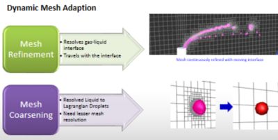
The heart of this VOF to DPM model is an algorithm that looks for liquid lumps that get separated from the main liquid body of the spray and then converts them into point masses for further tracking. This method allows us to not track the interface of smaller drops and hence reduces the need to have very fine meshes. A second important piece of this hybrid model is the dynamic mesh refinement and coarsening. Users can employ a new adaption method, called polyhedral unstructured mesh adaptation or PUMA, to adapt even polyhedral cells. Interface areas are tracked with fine mesh and once a blob is identified for transfer to the DPM model, the local mesh is coarsened to keep the cell count manageable. As a result, the dynamic adaption keeps the cell count in check, much reducing the computation resources required. An example of such adaptation is shown in the picture below.
Fluent VOF to DPM CFD Spray Model Examples
This new model has gone through rigorous testing and several cases have been run successfully to completion. The best practice documents and tutorials are also available upon request from Ansys Support on the Ansys Customer Portal. Here are a few examples below to show what type of output that we can obtain.
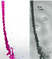
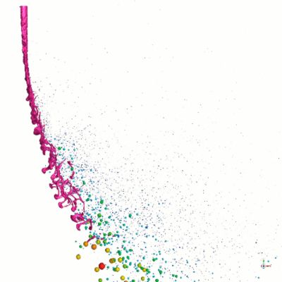
The CFD spray image below shows a turbulent liquid jet deforming in a crossflow. A combination of nozzle turbulence and crossflow inertia break the jet into droplets. The overall jet trajectory and waves leading to breakup were captured correctly. In addition to VOF and DPM variables, a user can access several data quantities on blob statistics.
The animation below shows the liquid jet formation, its breakup and the creation of DPM droplets from the blobs.
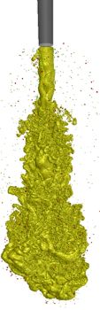
The figure below shows a fuel injector where high pressure liquid hydrocarbon fuel is injected into a chamber. The development of the jet and subsequent droplet formation can be seen.
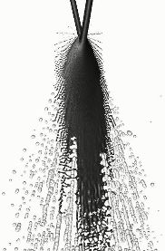
This double impinging jet shows in dark color the part of the spray that is resolved in the VOF formulation and in light color the drops that have been converted and are now tracked as point masses. Note that the latter are shown in supranatural size to make them more visible.
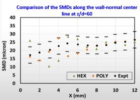
The particle size data is compared against experiment using the Sauter Mean Diameter values for a jet in cross flow test case. The results are within an acceptable variation of 10%. This is remarkable considering the results are based on actual modeling of the liquid interface and its breakup and hence makes it possible to be able to use simulation to predict a spray nozzle performance.
We hope you find this hybrid model useful. If you'd like to learn more, please contact us. We would love to show this new model and help you speed your own spray simulations.
Or try it for yourself with a free trial of Ansys Fluent.