-
-
학생용 무료 소프트웨어에 액세스하기
차세대 엔지니어에게 힘을 실어주는 Ansys
학생들은 세계적 수준의 시뮬레이션 소프트웨어를 무료로 이용할 수 있습니다.
-
지금 바로 Ansys에 연결하십시오!
미래를 설계하기
시뮬레이션이 다음 혁신을 어떻게 지원할 수 있는지 알아보려면 Ansys와 연결하십시오.
국가
무료 트라이얼
제품 및 서비스
학습하기
회사 정보
Back
제품 및 서비스
ANSYS BLOG
March 20, 2023
Creating Prismatic Lightguides to Easily Direct Light for Illumination
Lightguides are pipelike optical structures that can be used to bring light from one point to another with minimum light loss. They are increasingly used in the automotive illumination market, in which features such as side mirror-mounted turn signals and indirect interior console lighting require rigorous control of light rays to produce effects that are both functional and pleasing, and, especially in the case of exterior automotive lighting, compliant with manufacturing regulations.
When designing for these applications, optical engineers need easy, reliable methods for guiding light. They require methods for simulating the lightguides they incorporate into their designs with enough precision to maximize the efficiency of the light that reaches the final illumination. Likewise, they require efficiency in the processes they follow to run successive simulations in a timely way that enables the necessary refinement to achieve their desired results.
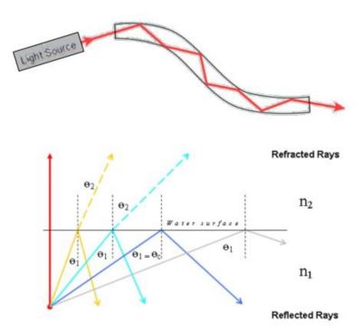
To be effective, a lightguide must bring light from a source not visible to the user, such as coming from behind an object or surface, to another surface to provide illumination. Lightguides rely on total internal reflection (TIR) to bring light from the LED source to the illuminated area. TIR happens when the light is incident to a surface at an angle greater than the critical angle. Rays in TIR stay within the lightguide, as shown in Figure 1. To extract light, an optical designer can introduce an intentional error, thus changing the light's direction and breaking the TIR, as shown in Figure 2.

Figure 1. Modification of a lightguide using an extraction geometry that converts a refracted system into transmitted light.
The geometry used for extracting light is often as simple as a rough surface that has been sandblasted or laser coded into the back side of the lightguide. In other designs, small spheres or other microstructures can be used for this purpose, which is common in backlit illumination like in computer monitor displays. But both methods are highly impacted by production tolerances and tooling limitations, making them less predictable and more difficult to control. For designers of automotive illumination systems, this control is essential for producing the quality of illumination that the system requires.
Using Prisms to Easily Generate and Control Light Quality
In lieu of rough surfaces or spheres, optical designers can add prisms to a lightguide to extract light. Because prisms have well-defined structures, they have two key advantages in this application: They make it easy to direct light in specific directions, and they also make it easy to define how much light will be extracted.
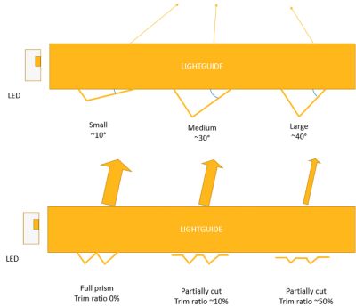
These two factors — extraction direction and extraction amount — form the main parameters for designing and optimizing a lightguide. The angle you specify and the amount by which you trim the extraction ratio will determine the direction and quality of the illumination, as shown in Figure 2.

Figure 2. The end angle of a lightguide controls the direction of light output (above), while precisely trimming the extraction ratio controls the quality of the light (below).
For optical designers, these parametric controls are the key to producing a lightguide that will best support their illumination design. Ensuring optical quality requires the precision of running iterative simulations, and staying on schedule to produce market-ready illumination products requires performing this analysis with speed and ease. For these reasons, prisms offer an ideal method for producing illumination that dovetails well with the requirements of a typical optical project.
In an upcoming blog, we'll take a look at how the Light Guide feature in Ansys Speos enables optical designers to rapidly simulate and refine lightguide designs, as well as how they can use Ansys optiSLang to streamline their design process.
To follow detailed steps for creating a prismatic lightguide in Speos, read this App Gallery article.