-
-
학생용 무료 소프트웨어에 액세스하기
차세대 엔지니어에게 힘을 실어주는 Ansys
학생들은 세계적 수준의 시뮬레이션 소프트웨어를 무료로 이용할 수 있습니다.
-
지금 바로 Ansys에 연결하십시오!
미래를 설계하기
시뮬레이션이 다음 혁신을 어떻게 지원할 수 있는지 알아보려면 Ansys와 연결하십시오.
무료 트라이얼
제품 및 서비스
학습하기
회사 정보
Back
제품 및 서비스
ANSYS BLOG
October 4, 2021
What 2D Skew Modeling Brings to NVH Simulations
Designing electric machines for automotive applications requires engineers to achieve two critical goals at the same time: maximizing the torque profile over a wide range of speeds and reducing the torque ripple by making the torque as smooth as possible. Torque ripple during the drive cycle is reflected in acoustic noises, and at higher speeds might become a source of audible noise pollution for passengers. In more industrial applications, where the electrical machine is connected through power electronics components to electric grids, torque ripple might impact the quality of the power generated back to the grid. Thus, it is important to reduce the electromagnetic torque ripple and associated noises, both mechanically and electromagnetically.
Additionally, the simulation speed and level of accuracy are equally important when finite element analysis (FEA) is applied to electrical machine design. In nearly every case, the trade-off between simulation speed and simulation accuracy is not something designers are willing to consider because both are critical.
In many cases, a 2D cross-section of the 3D geometry is chosen for electromagnetic modeling purposes. In some of these cases, the biggest question is if the 2D model will achieve the required accuracy. For example, there are reasons why a 2D cross-section for radial field electrical machines has limitations in accounting for 3D effects – e.g., end-windings, different axial lengths of both the stator and rotor, different types of eccentricity, or skew topologies of various rotor or stator designs as shown in Figures 1 and 2 respectively.
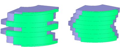
Figure 1. Permanent magnet skewed rotor topologies, including a customized skew configuration (left) and a V-shaped skew configuration (right).
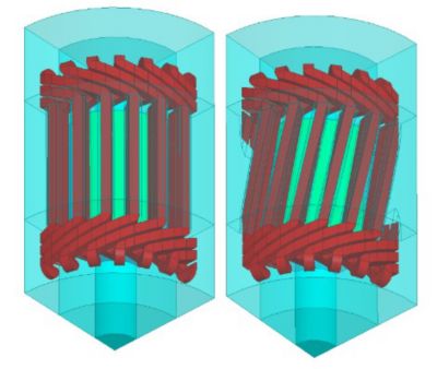
Figure 2. A fraction of 3D geometry of an electrical machine design showing straight stator slots (left) and skewed stator slots (right).
Because motor skew is inherently a 3D phenomenon, let’s consider the latter case where the electrical machine topology includes a skew configuration. In Figure 3, a 3D FEA simulation result shows the difference between torque ripple for a skewed and non-skewed machine. And while this 3D approach achieves the desired accuracy of the solution, it does not address the fast simulation speed required by the design process due to longer 3D simulation times.
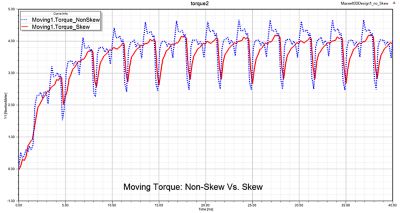
Figure 3. A time varying electromagnetic torque chart showing a 3D solution comparison between skew and non-skew stator topology.

Figure 4. A time varying electromagnetic torque chart showing a 2D solution comparison between skew and non-skew stator topology.
Get 2D Simulation Speed With 3D Accuracy
To address these challenges, Ansys Maxwell introduces a mathematical algorithm enabling designers to take advantage of 2D FEA speed while preserving the accuracy of 3D FEA simulation. It seems challenging, if not impossible, but with new technology developed to account for skewed rotor and stator electrical machine configurations, this task became achievable and more practical in the Ansys 2021 R2 release. Figure 4 shows torque ripple using a 2D model using this new algorithm for both a skewed and non-skewed machine, achieving very good agreement as compared to the 3D model from Figure 3.
Maxwell provides a customizable skew configuration in its user interface where engineers can define their own rotor/stator skew topology. Maxwell 2D transient solver employs a multi-slice algorithm to compute the dynamic performance of the electrical machine. While the speed of 2D FEA is much faster than 3D, Maxwell additionally delivers a high-performance computing (HPC) solution to distribute finite element computation of each slice to one message passing interface (MPI) task by employing a parallel block matrix solving scheme. This makes the results of any skew-based topology an easy and fast solution to perform.
Because the electric machine skewing scheme has an impact on torque ripple, it is imperative that a fast and accurate workflow exists to evaluate the impact this has on the acoustic noise during the drive cycle. Thus, the electromagnetic forces are computed on each slice of the 2D model and passed to the harmonic mechanical solver to perform noise, vibration & harshness (NVH) analysis (Figure 5).
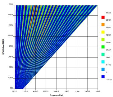
Figure 5. Waterfall diagram showing sound pressure level (SPL) vs rotor speed and excitation frequency.
Learn More About Ansys Maxwell
In addition to the skew enhancements, the Maxwell 2021 R2 update has even more in store.
For example, to enhance thermal management for topologies with permanent magnets, Maxwell now supports multiple temperature-dependent demagnetization characteristics, preserving the shapes of input curves.
Finally, I cannot finish this blog without highlighting specific enhancements to NVH, which covers more practical applications for increasing levels of accuracy:
- Options of window function for Discrete Fourier Transformation
- Object-based harmonic force calculation with arbitrary skew slice model
- Added anisotropic elastic properties for enhanced magnetostriction force modeling
For more details, watch the Ansys 2021 R2 Maxwell webinar.