


ANSYS ADVANTAGE MAGAZINE
DATE: 2018
Simulation and Additive Manufacturing Speed Tooling Design
By Mark Davey, Principal Engineer, Senior Flexonics Inc., Bartlett, USA
When tooling suppliers told Senior Flexonics engineers that considerable troubleshooting and cost would be required to validate tooling to manufacture finned tubes for a new compact liquid/air heat exchanger, they turned to Ansys software. Employing Ansys LS-DYNA to simulate the stamping operation allowed them to design a progressive die prototype right the first time. They were able to produce the tool at a 95 percent lower cost and in 75 percent less time than the best supplier quote.
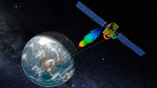
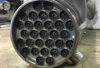
Senior Flexonics is developing a next-generation compact liquid/air heat exchanger (HEX) for multiple industrial and mobile applications. By using finned tubes to increase the heat transfer between the hot gas in the tubes and the cold water in the shell, the new HEX is smaller and lighter than current models. However, these finned tubes are challenging to manufacture because the high height-to-width ratio of the fins makes stamping difficult due to very high stresses and strains on both the raw sheet and the progressive die. When the company took this new design to its two tooling suppliers, one said they could not do it and the other said it would take 12 weeks and cost $60,000 because a lengthy trial-and-error process on the shop floor would be required to make a reliable tool. Senior Flexonics engineers decided to simulate the stamping operation using Ansys LS-DYNA explicit dynamics software to speed the tool prototyping process. Simulation made it possible to identify and correct problems in an existing original progressive die design, select the right part material and validate the process of bending the finned sheets into a cylinder. Using additive manufacturing (3D printing), tooling developed employing simulation arrived in only three weeks, at a cost of $3,000, and worked perfectly the first time.
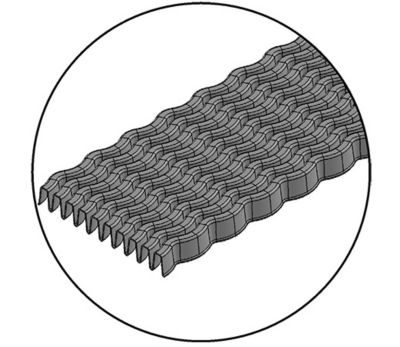
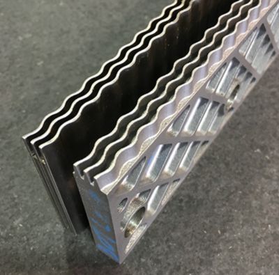
The first step in the manufacturing process is to stamp fins into a flat pattern.

The first step in the manufacturing process is to stamp fins into a flat pattern.
"Simulation made it possible to obtain appropriate dies on first delivery, which saved tens of thousands of dollars and enabled the company to meet the product launch schedule."
NEW-GENERATION HEX
Senior Flexonics produces industrial heat exchangers, as well as EGR coolers for heavy-, medium- and light-duty trucks, high-pressure diesel fuel tubes and rails, water tubes, turbo oil drain lines, metal bellows, piston cooling jets, and complex assemblies. The company’s engineers designed its newest HEX to increase heat conduction between the hot and cold fluids so that the cooler was smaller and lighter, both important advantages in the automotive and trucking markets. To do this, they designed longitudinal fins within the tubes that increase the contact area between the hot gas in the tubes and the cold liquid in the shell of the heat exchanger.
When Senior Flexonics engineers asked their tooling suppliers for quotes to build the progressive die tooling needed to manufacture the fins, the suppliers pointed out that the depth of the fins forced the stainless steel material to the edge of its formability limits. They said it would be very difficult to predict in advance a tooling geometry that would provide the correct final shape. They were also concerned about tearing in high-stress areas. They expected that a trial-and-error process would be required to meet the design specifications.

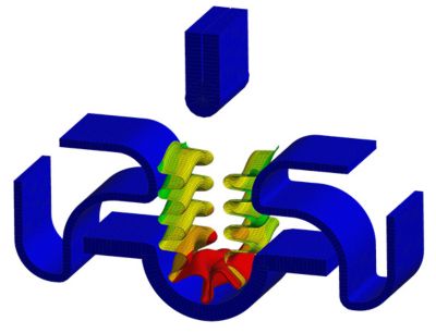
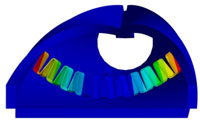
Simulation identified problems with fins produced by existing progressive die design.
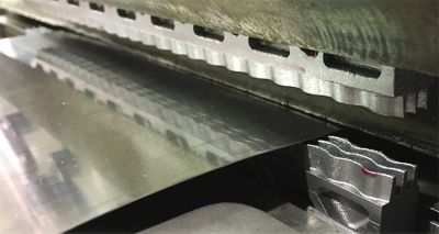
Printed tooling installed in stamping press
Original tools (left) and 3D printed tools (right)
SIMULATING THE STAMPING OPERATION
Senior Flexonics engineers decided to design the tool internally and to contract a 3D printing service bureau to build it. The engineers were not familiar with Ansys LS-DYNA, but they were able to quickly and easily set up the simulation due to their familiarity with the Ansys Workbench environment. They extracted an initial tool design in CAD software and opened the CAD model in Workbench. Engineers generated the finite element mesh in Workbench using the automatic multizone method. They modeled the tool as 17-4 PH stainless steel solid elements and the raw material as 400-series stainless steel shell elements. The model included 64,230 nodes and 67,112 elements. To model a strip of material pulled out of a feed chute they used a friction element to apply forces to mimic those required to unwind and pretension the strip from the coil. Engineers wrote a user-defined function to describe a time-dependent sinusoidal displacement function that provides gradual startup and slowdown on each stroke of the die to ensure a stable solution.
Ansys LS-DYNA iterated to a transient solution of four stamping cycles in 38 hours. The simulation displacement results showed that the part produced by an existing initial tool design would have curled at its crown and walls where it was supposed to be relatively flat, and that the radius at the root of the fin was too large. The strip-forming strain results showed considerable tearing. Based on the simulation results, Senior Flexonics engineers adjusted the tool geometry to counteract the distortion problems. They changed the material to 316L stainless steel to address the tearing problem. After only a couple of iterations, the simulation predicted that the new progressive die design would produce parts of the right geometry and limit tearing to just the first fin on the strip, which was acceptable. The tooling stress results showed that the tooling could easily withstand the forming process. Based on these results, Senior Flexonics engineers ordered the prototype tool from a 3D printing service bureau.
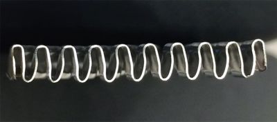
Compression bending did not properly seal tubes.
First fins produced on existing tool matched simulation predictions.
SIMULATING THE TUBE FORMING OPERATION
While they waited for the progressive die to be delivered, Senior Flexonics engineers turned their attention to developing a process to form the finned strip into a cylinder for insertion into a tube. They first used LS-DYNA to simulate a compression bending technique. The simulation results showed that this approach would not bring the ends of the fins together to form a full cylinder. Next, they simulated a tangential wiping system, but this method also did not fully close off the cylinder. Finally, they simulated a rolling process that provided considerably better results but still did not quite fully form the cylinder. Engineers modified the rolling die design, decreasing the diameter at the outlet so that the rolled cylinder popped out of the tool for springback insertion into a tube. Simulation showed that this approach provided a tight seam, so the rolling die was also procured from a 3D printing service bureau.
When the prototype progressive die was received, Senior Flexonics engineers installed it in a stamping press and ran a short strip. The results closely matched the simulation predictions and met all Second fins produced on optimized 3D printed tool matched revised simulation predictions. Second-generation rolling die correctly seals tubes. design specifications. The rolling die also matched the simulation by working correctly the first time. Without simulation, the chances are that both the progressive die and the rolling die would have required expensive repairs and possibly even rebuilding to resolve the problems that were identified in simulation. Simulation made it possible to obtain appropriate dies on first delivery, which saved tens of thousands of dollars and enabled the company to meet the product development schedule.
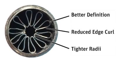
Second fins produced on optimized 3D printed tool matched revised simulation predictions.
Second-generation rolling die correctly seals tubes.
시작하기
엔지니어링 과제에 직면하고 있다면우리 팀이 도와드리겠습니다. 풍부한 경험과 혁신에 대한 헌신을 가지고 있는 우리에게 연락해 주십시오. 협력을 통해 엔지니어링 문제를 성장과 성공의 기회로 바꾸십시오. 지금 문의하기
