Synopsys and Ansys power the future of innovation—connecting silicon to systems.
什麼是相控陣列天線?
相控陣列天線是由多個基本天線元件組成的陣列,彼此協同運作如同單一天線,透過電子方式導引無線電波,指向一個或多個方向,而無需進行任何實體移動。
在一種稱為波束成形的過程中,相控陣列系統會從每個天線元件發出相同頻率的訊號,但各元件的相位與幅度則有所不同。此舉會使無線電波產生建設性與破壞性的干涉,進而形成一個具有方向性與高增益的波束輻射圖樣。
大多數相控陣列天線為平面型,由數百甚至數千個單一元件構成的陣列組成,排列方式可能是線性、單一平面或三維結構。工程師透過模擬技術,應用高頻電磁學的原理來設計陣列元件、整體陣列配置,以及驅動天線的射頻 (RF) 硬體與電子電路。
相控陣列天線的基本原理
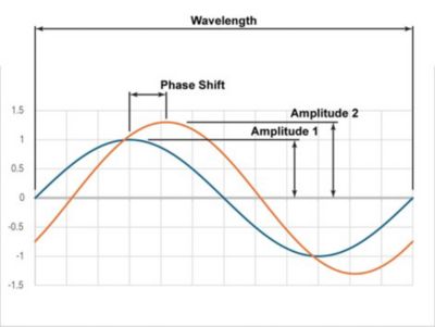
兩個具有相同頻率但相位與振幅有所偏移的訊號簡化圖示
波長是波在一個週期內傳遞的距離。振幅是波的最大值,而相位則是各波峰之間的差異或時間延遲。在相控陣列天線中,頻率通常保持恆定,僅有微小變化,但每個天線的相位與振幅皆可調整。
天線元件
天線元件是組成陣列的單一天線。雖然有許多不同類型的天線元件可用於組成陣列,但最常見的天線元件包括補片天線、微帶補片天線、波導號角與單極天線。天線的工作頻率決定了元件的尺寸與間距。
天線增益
天線增益是指在任一方向上,訊號的強度 (振幅) 相較於理論上的單一等向輻射源而言的數值,後者會將訊號均勻地向所有方向發射。
相控陣列天線波束成形器元件
波束成形器由電子與射頻電路組成,用於將輸入訊號轉換為可導引的發射訊號。對於被動式相控陣列系統 — 最常見的相控陣列天線類型 — 單一輸入訊號會透過一系列元件轉換為指向目標方向的訊號:包括發射功率放大器、波束成形器,以及個別的天線元件。波束成形器通常包含衰減器、相移器,或具備類似功能的元件。
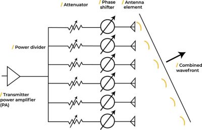
一組用於產生特定寬度與方向之訊號的關鍵元件電路示意圖
- 收發器功率放大器 (PA):將輸入訊號放大,以產生所需增益的目標訊號。這是接收器將會接收與測量的訊號。
- 功率分配器:功率分配器會將輸入訊號分成多路訊號,分配給每個天線元件電路。
- 衰減器:每個天線元件的振幅可透過衰減器依需求進行增加或減少。這些裝置可以是數位或類比類型,並可分為被動式或主動式。
- 相移器:這些數位或類比裝置會對波形引入微小延遲,是導引波束的關鍵步驟。
- 天線元件:最後,訊號傳送至天線元件,並以所需的相位與振幅進行發射。
- 低噪音放大器 (LNA):若天線同時作為接收天線使用,則會包含一個低噪音放大器。
- 收發切換開關:若天線同時用於接收訊號,則切換開關會使進入的訊號經由 LNA 傳遞,而非透過發射功率放大器。
控制相控陣列的電腦會以電子方式調整每個天線元件的振幅與相位,並能快速進行變更,以便迅速改變波束方向。
波束方向
波束方向是從天線原點指向訊號合成後最大強度所在位置的方向。天線設計會使用兩個角度來定義此向量。方位角為平行於地平線的角度,仰角則是高於地平線的角度。
波束寬度
將訊號振幅對照導引角度繪圖後,可觀察到由相控陣列產生的主波束與其他波束在圖上呈現駝峰狀,稱為波瓣。波束寬度是指最強波瓣的角度寬度。
波束寬度的測量方式有兩種標準。第一種是從零點位置到零點位置的測量,稱為第一零點波束寬度 (FNBW)。第二種方法是在峰值向下衰減一半功率處進行測量,稱為半功率波束寬度 (HPBW)。
波束導引與掃描
以電子方式設定波束方向稱為波束導引。當波束方向依特定模式移動時,則稱為波束掃描。更複雜的相控陣列天線可同時導引多個波束,朝不同方向發射,且各波束頻率略有差異。
旁波瓣
旁波瓣是指輻射圖樣中除了主波束之外的局部最大值。旁波瓣會浪費能量,並可能造成干擾。陣列設計的目標是盡可能降低旁波瓣的強度。
相控陣列天線的類型
相控陣列天線可以有多種形式。專家透過拓撲與波束成形器技術對不同類型的相控陣列天線進行分類。
相控陣列拓撲
區分相控陣列系統類型的一種方式,是依據天線元件的相對位置進行分類。大多數系統可歸類為以下幾種相控陣列拓撲類型之一:
- 線性 (1D) 陣列:天線元件排列成水平線時可改變波束的方位角,排列成垂直線時則可控制仰角。
- 平面 (2D) 陣列:天線元件排列於平坦表面 (平面結構) 上,可同時導引仰角與方位角,涵蓋天線上方的整個空間。
- 3D 陣列:天線元件分佈於空間體積中,可導引一個或多個波束至任意方向。
波束成形器的類型
被動式電子掃描陣列 (PESA):被動式相控陣列是一種整體共用單一收發器的天線。這是最常見的相控陣列配置類型。
主動式電子掃描陣列 (AESA):主動式相控陣列是指每個天線元件或部分元件子集皆配有類比收發模組,用以產生各元件所需的相位偏移。軍事應用通常採用此較為先進的技術。
數位波束成形 (DBF) 相控陣列:DBF 陣列天線使用數位收發模組調整每個天線元件的相位與振幅。它也可產生多個波束,並透過現場可程式化閘陣列 (FPGA) 晶片或陣列電腦以數位方式形成天線圖樣。數位波束成形陣列亦可建立輻射圖樣中的零點,以降低功率敏感度,並刻意減少接收靈敏度,以減輕來自已知方向的干擾或對其造成的干擾。
混合式波束成形相控陣列:AESA 與 DBF 方法可以結合,形成混合式波束成形相控陣列。這種方法包含子陣列。每個子陣列配備一組類比收發器,且子陣列中的每個陣列元件皆配有自己的數位收發器。這方法可產生多組同時發射的波束叢集。
相控陣列天線的優勢與應用
設計通訊系統與感應器的工程師會使用相控陣列天線來建立具備空間選擇性的無線 RF 訊號源。天線陣列使系統得以具備以下一項或多項功能:
- 結合多個天線元件,形成更大的孔徑與更強的訊號
- 透過波束成形建立可電子導引的天線
- 使用自適應、混合式或數位波束成形,同時產生多個指向不同方向的波束,並盡量減少與其他 RF 系統之間的干擾
上述功能相較於傳統的機械轉向反射式與桅桿式天線,提供顯著優勢:
- 電子導引波束可進行更快速的掃描,或極速切換波束方向。
- 相較於具備機械轉向反射式與大型天線盤的天線系統,相控陣列天線通常佔用的空間較少且重量較輕。它可安裝於車輛表面或建築物上。
- 在多數情況下,相控陣列系統可在相同性能下具備較低成本,尤其當使用積體電路 (IC) 來執行波束成形或驅動天線元件時更為顯著。
- 可靠性。單一通道中的元件即使發生故障,也不會影響整體天線系統的基本性能。實際上,當元件發生故障時,系統性能會逐漸下降,與機械天線系統存在單點故障風險相比,可靠性更高。
- 可透過單一裝置將訊號指向多個方向。
- 由於每個天線元件的功率會累加,因此整體能效更高。
這些優勢促使早期的 RF 先驅發展出相控陣列雷達與射電天文陣列,以增強來自遙遠恆星的微弱訊號。隨著時間推移,相控陣列的應用領域不斷擴展,涵蓋其他航太系統、醫療、汽車、工業與通訊系統等天線應用。
多方向陣列天線系統可實現:
- 現代 4G 與 5G 通訊網路
- 未來的 6G 通訊網路
- 最新的 WiFi 存取點
- 自動駕駛車用雷達系統
- 治療用醫療裝置
模擬如何實現相控陣列天線設計
如果沒有模擬,即使是設計小型的相控陣列天線也相當困難,對於含有數千個天線元件的系統而言,模擬更是不可或缺。從陣列間距到旁波瓣損失等所有設計參數,手動計算都非常困難。在無響室中量測輻射圖樣的成本高昂且耗時。

模擬動畫展示了相控陣列天線的最大增益如何在軌道運行過程中動態對準地面站
透過模擬,工程師不僅能設計陣列與波束成形元件,還能就效率、成本與速度對整體系統進行最佳化。團隊也會利用模擬來了解製造公差與材料變異對設計的影響。
工程師運用模擬工具設計、驗證並最佳化天線陣列、天線元件與波束成形元件。他們也能模擬天線如何與整個系統互動。
像 Ansys HFSS 高頻電磁學模擬軟體這類功能完整、易於使用且精準的高頻電磁學有限元素模擬工具,幾乎適用於模擬相控陣列天線的所有電磁層面。HFSS 搭載強大的網格劃分技術、平行求解器,以及專為陣列打造的工作流程,是元件與系統層級建模的黃金標準。HFSS 軟體可模擬從單一波導到整個組件的訊號傳播,讓天線在硬體尚未製作之前即完成建模。
在 Ansys Perceive EM 射頻通道與雷達訊號模擬軟體這類應用中所採用的射線追蹤與反射技術,可將模擬提升至全新層次,讓使用者能夠建模其天線在長距離傳輸以及如倉庫貨架或城市建築等障礙物周圍的效能表現。為了模擬天線系統安裝對周圍環境的影響,設計團隊會使用 HFSS 軟體內的射線追蹤與反射 (SBR) 功能,以捕捉天線與其安裝結構如塔柱、建築物或車輛之間的自耦效應。工程師也可以使用模擬,搭配如 Ansys RF Channel Modeler 高擬真無線通道建模軟體這類系統層級工具,建構其天線設計在網路中的運作模式。
當電磁特性被充分理解並完成最佳化後,設計團隊便需評估相控陣列系統的熱效應與結構反應。他們可以使用像 Ansys Mechanical 結構有限元素分析 (FEA) 軟體或Ansys Icepak 電子散熱模擬軟體這類工具,這些工具可與其高頻電磁模擬解算器進行整合。若天線安裝於車輛或飛行器上,他們可能需要使用 CFD 工具,例如 Ansys Fluent 流體模擬軟體,以瞭解並設計針對高速下的空氣動力負載。
相關資源
讓我們開始吧
如果您面臨工程挑戰,我們的團隊將隨時為您提供協助。憑藉豐富的經驗和對創新的承諾,我們邀請您與我們聯絡。讓我們共同合作,將您的工程障礙轉化為成長和成功的機會。立即與我們聯絡,開始對話。