Synopsys and Ansys power the future of innovation—connecting silicon to systems.
-
-
Kostenlose Software für Studierende
Ansys unterstützt die nächste Generation von Ingenieur*innen
Studenten erhalten kostenlosen Zugang zu erstklassiger Simulationssoftware.
-
Verbinden Sie sich jetzt mit Ansys!
Gestalten Sie Ihre Zukunft
Stellen Sie eine Verbindung mit Ansys her, um zu erfahren, wie Simulation Ihren nächsten Durchbruch vorantreiben kann.
Kostenlose Demoversionen
Produkte & Dienstleistungen
Lernportal
Über das Unternehmen
Back
Produkte & Dienstleistungen
Back
Lernportal
Ansys unterstützt die nächste Generation von Ingenieur*innen
Studenten erhalten kostenlosen Zugang zu erstklassiger Simulationssoftware.
Back
Über das Unternehmen
Gestalten Sie Ihre Zukunft
Stellen Sie eine Verbindung mit Ansys her, um zu erfahren, wie Simulation Ihren nächsten Durchbruch vorantreiben kann.
Kostenlose Demoversionen
ANSYS ADVANTAGE MAGAZINE
DATE: 2020
Simulation: Leading the Pack
By Xiao Hu
Principal Application Engineer Ansys, Ann Arbor, U.S.A.

Lithium-ion battery packs are the heart of the coming electrical vehicle (EV) revolution. IEA, the International Energy Agency, thinks the number of electric passenger vehicles could exceed 130 million or even 250 million vehicles by 2030, depending on policy changes and industry pledge fulfillment.1 In its 2018 prediction, OPEC, the Organization of Petroleum Exporting Countries, more conservatively estimated 300 million electric vehicles in the global car fleet by 2040.2 In its Electric Vehicle Outlook 2019, Bloomberg New Energy Finance (BNEF) was more bullish on EVs, predicting 500 million passenger EVs on the road by 2040, which would be about 32% of the world’s passenger vehicles.3 They may disagree on timing and numbers, but analysts and automotive industry investments all point to a bright future for EVs.
Before EV sales can compete with those of cars with internal combustion engines, they must approach price parity. And, because EV battery packs make up the lion’s share of EV costs, the pressure is on engineering teams to quickly and cost-effectively optimize battery performance. To do that requires simulation. One of the key applications in simulation performed by battery designers is the electro-thermal coupled (ETC) analysis. There are two types of ETC analyses.
The first couples a thermal computational fluid dynamics (CFD) model with a battery sub-model for electrical performance. A popular choice of such a sub-model is a battery equivalent circuit model (ECM). This type of ETC is commonly referred to as battery thermal management analysis.
Battery thermal management analysis benefits from an ETC that involves a high-resolution CFD simulation. Ansys Fluent software can simulate the temperature distribution in a battery pack, as well as the entire battery cooling system with a battery ECM for heat generation, to allow for battery thermal management optimization.
By using Ansys Fluent and Ansys Twin Builder, an entire battery pack can be simulated in far less time than with other popular techniques.
The second type of ETC is tailored for system applications, in which the battery ECM is also used for the electrical side, but is coupled with a fast thermal model. Many system applications do not require a high-fidelity temperature solution in a battery pack. In fact, for system-level applications, that high fidelity provides extraneous detail and demands more computational resources. For such a system application, a different approach is needed. A popular choice for thermal analysis in system applications is a thermal network model.
However, it can be difficult to create an accurate thermal network model because it requires a significant level of expertise. Plus, it is still relatively time-consuming and prone to errors. Another methodology, reduced-order modeling (ROM), can be used to replace the thermal network approach to develop a battery pack simulation for system applications. This ROM approach can speed up ETC by an order of magnitude compared to using the thermal network approach, and it takes less than half a man-hour to create the thermal ROM. The ROM methodology is also more accurate than the thermal network model.
Multiple Use Cases for System-level Battery Pack Coupling
A battery ETC for system applications demands speed and accuracy. In some cases, it demands real-time or close to real-time performance with compromised accuracy. In other cases, it requires improved accuracy at the cost of speed.
For example, a system integration engineer may need a battery ETC model to drive the entire electric powertrain system or a subset of it at close to real-time performance. The battery analysis, being a component in the entire system, cannot be allowed to consume more than its share of computational resources. For the entire system model to function at an acceptable speed, the battery module or even entire battery pack may be lumped into one single battery ETC. In such a scaled battery model, there is only one set of electrical parameters for the entire pack; for instance, there is one state-of-charge (SoC) value to represent the entire pack and perhaps one temperature for each battery module or even for the pack.
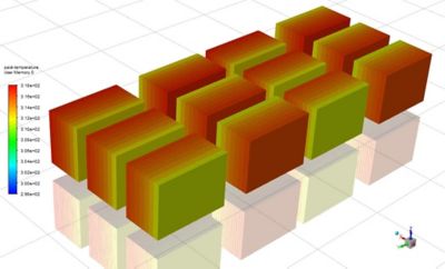
A thermal simulation of a battery module shows temperature variation in a module. The impact of such variation on battery electrical performance is simulated using ROM coupled with ECM. The ROM is calibrated using the CFD results shown.
For battery management system (BMS) designers, on the other hand, a detailed battery ETC model is required to test the battery BMS algorithm (see “Using Ansys MBSE Solutions for Battery Management System Applications”). The battery ETC model would need to accurately capture the temperature for each cell to be able to make sure that cell-to-cell temperature variation is lower than the acceptable level. Such a battery ETC model would also need to monitor electrical performance, for instance the SoC, for each cell. As a result, it would demand a completely discretized pack ETC model.
The above examples represent two extreme cases, but there are many applications that demand a level of discretization somewhere in the middle. A methodology for battery pack–level ETC should offer the flexibility to satisfy the requirements of both extreme cases and everything in between. Ansys has developed a methodology to accommodate all of them.
Using Reduced-order Modeling for Battery Coupling
To demonstrate the methodology, Ansys engineers start with a proposed battery pack ETC model that consists of an electrical part and a thermal part. The electrical part uses the battery ECM model with different levels of discretization. The thermal part uses ROMs calibrated from high-fidelity CFD results. The ROMs also provide a different level of discretization. The cooling effect of each module is modeled using heat transfer coefficients (HTCs).
The battery ECM is an industry standard for simulating battery electrical performance. A battery ECM can be used at the battery cell, module and pack levels to predict battery range, peak power and drive-cycle performance. Ansys Twin Builder provides a wizard to help customers build a battery ECM. The ECM from Ansys Twin Builder could be state of charge, temperature, discharge/charge and rate dependent. The wizard builds the cell-level ECM typically from hybrid pulse power characterization (HPPC) data. It could also build a cell-level ECM from customer parameters. The ECM from Twin Builder accommodates both 4P (one resistor–capacitor) and 6P (two RCs) types of ECM models. The wizard can also build a module-level ECM from a cell-level ECM given a module configuration of mSnP. (A battery module consists of n parallel branches with each branch having m cells.) At the module level, the wizard builds a discretized version for BMS applications in which detailed information for each cell is necessary, or a scaled version for system integration applications in which fast simulation is important. An engineer can complete a pack ECM in just a few minutes using Twin Builder.
When cracks appeared in a gear shifter bracket, RCR engineers used Ansys Mechanical to find the cause and then designed an optimized bracket (shown above).
Using reduced order models for conjugate heat transfer (CHT) is a tried-and-true technique that has been used in electronics for many years. The new methodology adopts this technique for the thermal part of a battery pack ETC. ROMs require training data to determine the thermal impedance of the battery system. In this methodology, Ansys engineers use Fluent to make a high-fidelity CHT model of the battery module to create the required training data. One CFD model for a module of 14S1P configuration (14 cells in series with 1 parallel branch) can be created using Fluent in half a day. The training data generation takes a couple of CPU hours. From the training data, a thermal ROM can be generated in a couple of minutes. Once the ROM is created, the CFD model is no longer needed for battery pack simulation. The ROM can be used to simulate temperature given any transient heat source.
Such a method can then be extended to the pack level. Because each module has the same geometry but sits at a different location on the cold plate, there is no need to create a pack CFD model. Instead, the thermal ROM is created for one module only. Different modules will have different heat transfer coefficient boundaries depending on where they sit on the cold plate. In this example, 12 thermal ROMs are each connected with their different HTC boundaries present in 12 different modules sitting at different locations on the cold plate.

The global stock of electric passenger cars passed 5 million in 2018, according to IEA, an organization focused on sustainability..
Because the HTC varies based on where each module sits on the battery cold plate, the cold plate must be meshed to account for the variability. A cold plate CHT analysis is a typical application of CFD. An unstructured CFD code like Fluent is well-suited to this analysis. After the cold plate CHT analysis, post-processing can be done to calculate the HTC for each module.
Once the ECM for the pack and the thermal ROMs for each module are created, it is simply a matter of connecting them together to create a two-way coupled ETC for the pack. A fully discretized version of a pack ETC has a run-time performance close to real time. A scaled version could run much faster depending on the amount of scaling adopted in the pack ETC model.
Once the pack-level ETC is simulated and the results are obtained, a detailed transient thermal analysis could be performed on any module using CFD, allowing it to be studied more closely. Plus, now that the CFD has the correct heat source from the system-level simulation, its results are more accurate. Better yet, a singular-value decomposition (SVD) ROM could be used to calculate the temperature using the correct heat source from the system-level model. The SVD ROM results differ from the CFD results by just a few percent, and it takes only minutes to simulate a 4-million polygon model.
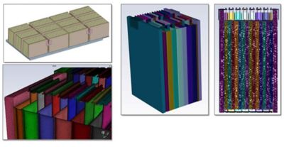
A template has been created inside Ansys Fluent to facilitate meshing a module. Only one module mesh is required, and different modules use different HTC boundaries.
Benefits of Using Ansys Battery Pack Simulation Technology
Ansys battery electro-thermal coupled models can also be seamlessly integrated into an existing system-level workflow. The ECM, the thermal ROM and the entire pack ETC model could be interconnected to third-party solutions via a functional mockup unit (FMU). This provides the flexibility to use Ansys battery models in other system tools. Let us take a look at two real-world examples. In the first example, Volkswagen Motorsport used Ansys battery ETC techniques on a pack for system integration. In the second example, A123, a leading cell manufacturer, used the Ansys battery model for BMS design.
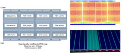
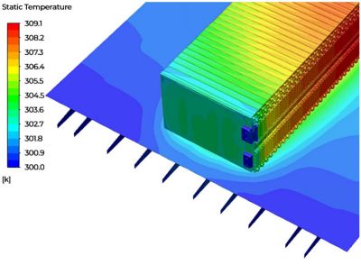
A heat transfer coefficient map of a cold plate (left) shows significant differences across the plate that must be accounted for in order to develop an electro-thermal coupling model for the entire pack.
When VW Motorsport engineers were challenged to build an electric vehicle in less than a year to compete in the 2018 Pikes Peak International Hill Climb, they needed an efficient method to design and validate the battery model. They used Ansys Fluent CFD results to identify the module thermal ROM. A temperature-sensitized battery-module ECM and the module thermal ROM were then two-way coupled in Ansys Twin Builder to form the complete battery module model. The modules were then connected to form a complete battery pack model for system-level simulation in a third-party solution. Their temperature results were excellent, all within 3 degrees, and the SoC results were within 10% of error compared with test results. The simulation method not only helped VW engineers meet their tight deadline, the resulting ID. R Pikes Peak race car crossed the finish line in record time. Learn more here.
A123 Systems LLC used the ROM methodology to build a discretized thermal ROM for a liquid-cooled, 48V battery pack. The accuracy and efficiency of the ROM were first validated by comparison with 3D simulation. The error from the ROM has shown to be negligible compared with the 3D CFD simulation. The thermal network was then compared with the ROM approach, and the errors from the thermal network were much higher compared with the ROM. Comparing the two methods’ workflows, ROM is a more systematic approach and less error prone. The discretized thermal ROM is then exported into a third-party system tool to develop a current derate algorithm for the BMS. The methodology demonstrated high capability and potential for dynamic identification of components overheating to protect the battery pack.
As automakers increasingly turn to electric powertrains, engineers will increasingly turn to time-saving techniques to optimize battery packs. The battery electro-thermal coupled model using ROM that Ansys has developed with its customers makes system-level battery pack applications more efficient, accurate and pervasive.
SOURCES
- IEA (2019), Global EV Outlook 2019, IEA, Paris, https://www.iea.org/reports/global-ev-outlook-2019
- 2019 World Oil Outlook 2040, OPEC, https://www.opec.org/opec_web/en/publications/340.htm
- BNEF (2019), 2019 Electric Vehicle Outlook, https://about.bnef.com/electric-vehicle-outlook