Synopsys and Ansys power the future of innovation—connecting silicon to systems.
-
-
Kostenlose Software für Studierende
Ansys unterstützt die nächste Generation von Ingenieur*innen
Studenten erhalten kostenlosen Zugang zu erstklassiger Simulationssoftware.
-
Verbinden Sie sich jetzt mit Ansys!
Gestalten Sie Ihre Zukunft
Stellen Sie eine Verbindung mit Ansys her, um zu erfahren, wie Simulation Ihren nächsten Durchbruch vorantreiben kann.
Kostenlose Demoversionen
Produkte & Dienstleistungen
Lernportal
Über das Unternehmen
Back
Produkte & Dienstleistungen
Back
Lernportal
Ansys unterstützt die nächste Generation von Ingenieur*innen
Studenten erhalten kostenlosen Zugang zu erstklassiger Simulationssoftware.
Back
Über das Unternehmen
Gestalten Sie Ihre Zukunft
Stellen Sie eine Verbindung mit Ansys her, um zu erfahren, wie Simulation Ihren nächsten Durchbruch vorantreiben kann.
Kostenlose Demoversionen
ANSYS ADVANTAGE MAGAZINE
DATE: 2020
Continental’s Guiding Light
By Vyacheslav Birman
Lighting Technology ExpertContinental Corporation and Ansys Advantage staff

While automobile dashboards increasingly use flat panel screens to display information like driving speed, engine temperature and fuel level, many automobile makers also incorporate physical dashboard components. Some automakers employ a hybrid digital–analog approach to meet customers’ needs. Others want to give drivers the retro feel of luxurious classic cars that digital readouts can’t match.
While automobile dashboards increasingly use flat panel screens to display information like driving speed, engine temperature and fuel level, many automobile makers also incorporate physical dashboard components like speedometer pointers. Some automakers employ a hybrid digital–analog approach to meet customers’ needs. Others want to give drivers the retro feel of luxurious classic cars that digital readouts can’t match. Like a person who wears a stylish wristwatch when they could easily read the time on their cell phone, some people will opt for analog aesthetics.
Continental Corporation has been helping automobile manufacturers distinguish their dashboard components over the years by designing illuminated pointers, horseshoe-shape speed displays and lighted rectangular panels powered by lightguides. The simplest lightguide design is a fiber optics cable illuminated by an LED at one end and transmitting that light out the other end. But it quickly gets more complicated. A simple arrow-shaped pointer with a “tip to tail” design made of polycarbonate (PC) or poly methyl methacrylate (PMMA) must be designed so that it is evenly illuminated from tip to tail, with no bright or dark spots, which involves the physics of total internal reflection (TIR) and controlled light leakage throughout the pointer. At this level, a physics-based optical simulation solver like Ansys Speos is required to analyze light propagation and scattering to produce virtual prototypes.
The most challenging dashboard pointer ever designed by Continental engineers involved a 3D, bowl-shaped speedometer gauge with a speedometer pointer that extended horizontally from the center until it reached the highly sloping walls of the bowl, at which point the pointer had to bend at a 45-degree angle. The horizontal section of the pointer extending from the origin to the bend was not illuminated. Evenly illuminating the upward sloping section from the bend to the tip of the pointer was a challenge that required almost 50 iterations of Speos simulations to get right.
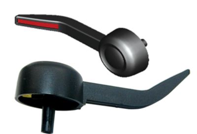
A 3D model of the speedometer pointer (top) and the actual pointer
CONTROLLING LIGHT LOSS
For total internal reflection (TIR), the surfaces of the lightguide must be polished to optical-level smoothness. Roughening the surface can change the angle at which incoming light rays impinge on the surface; those striking at less than the critical angle will pass through the surface as light leakage. Designers use this phenomenon by modifying surface roughness to cause light loss to illuminate a gauge or pointer.
Another, more common, method is to change the 3D geometry of the pointer so that the thickness of the pointer — its cross section at various points and the angles of its top, bottom and sides — varies in such a way as to promote uniform loss of light through the top surface that will be visible to the driver.
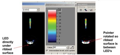
The results of final simulations performed for two pointer positions: the LED at the edges (right) and the LED underneath the middle of the receiving portion of the pointer (left)
SOLVING THE CHALLENGES OF A 45-DEGREE SPEEDOMETER POINTER
The abrupt change from 0 to 45 degrees over a small region in the proposed pointer was challenging enough that other companies turned the project down before illumination engineers at Continental decided to take it on. The main problem was a bright spot that appeared at the beginning of the bent area, as more light escaped through the extreme angle. Minimizing the brightness in that area was a primary goal.
In addition to the bend problem, a large number of pointer design parameters had to be optimized: the shape of the light housing dome, the shape and roughness of the receiving surface (the section of the pointer that receives the light, located at the beginning of the pointer in the center of the gauge above a set of LEDs), and the shapes of the reflecting surface and the bottom, top, left and right surfaces of the pointer. In most cases, two variables are used in achieving optimal illumination: the width of the bottom surface of the pointer and its slope.
Mechanical engineers at Continental created an initial geometry for the speedometer pointer, after which the illumination engineers imported it into Speos. The Speos software automatically created a mesh for the geometry. Then the illumination engineers specified the optical properties of the materials and surfaces, taking advantage of the huge library of materials in Speos. In this case they chose polycarbonate as the material, with surfaces polished to optical quality. Next, they specified the number of light rays, the location of an observer and the surface at which the observer is looking. Finally, they input the LED intensity — the light flux from LEDs — which depends on the amount of electrical current supplied to the LEDs. Speos simulated the luminance that the theoretical observer would see coming from the specified surface.
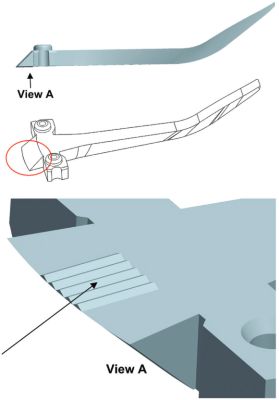
Ansys Speos helped Continental determine that adding five ribs to the receiving surface would evenly distribute luminance, regardless of the pointer position.
Running Speos simulations on the initial geometry revealed that the bright spot was still visible in the transition area from 0 to 45 degrees. The engineers took two approaches to resolve this. First, they changed the ratio of the top-to-bottom surface near the bend, with the larger top surface tapering into a truncated V shape at the bottom. The narrower the bottom surface, the less light that enters that area, resulting in less light loss, which minimizes the unwanted bright spot. In theory, the ideal shape at the bottom would be a point as at the bottom of a V, but manufacturability concerns dictated that the bottom width be at least 0.5 mm.
The second approach was to decrease the angle of the bottom surface of the pointer in the bend area. Even though the top slope was 45 degrees, the bottom slope, which is unseen by the driver, can curve more gently. As an approximation, if you assume all the light rays move horizontally, the larger the slope of the surface, the more that rays get reflected upward, so decreasing the slope would mean fewer rays being reflected upward, again minimizing the bright spot.
Furthermore, Speos indicated that adding a bump — a slight increase in thickness — on the top surface of the pointer just beyond the start of the bend would increase the percentage of vertically propagating rays experiencing total internal reflection, thereby reducing light loss in this area and minimizing the bright spot.
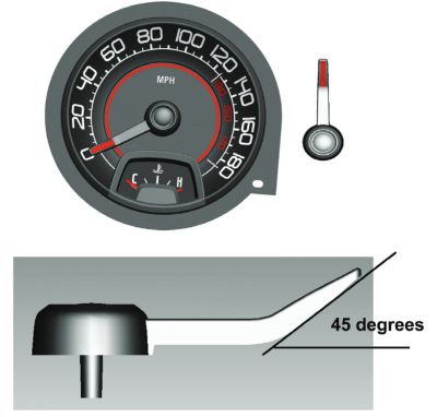
Designing a speedometer needle, or pointer, with a 45-degree angle to follow the bowl-shaped contour of a speedometer created lightguide illumination challenges that Continental used Ansys Speos to solve.
OPTIMIZING LED–POINTER POSITIONING
The receiving surface is a wide section at the base of the pointer that receives the light from an LED (or LEDs) underneath it. For this design, six LEDs were arranged on a circular base beneath the receiving surface.
Because the pointer, and therefore the receiving surface, changes its angular position as the pointer moves around the gauge — due to increasing or decreasing speed — the receiving surface is sometimes directly over an LED and sometimes between LEDs. As a result, the luminance distribution varied with pointer angle, an undesirable effect. The engineers decided to place vertical ribs on the underside of the receiving surface to redistribute the light reflected from the LEDs horizontally, thereby minimizing the variance in luminance caused by the relative position of the receiving surface to the LEDs. Using Speos, they ran simulations in which they varied the number of ribs and their spacing, ultimately settling on five ribs placed 0.5 mm apart. This solution resulted in evenly distributed luminance independent of the pointer position; it also minimized the bright spot when the center of the receiving surface was on top of an LED.
THE VALUE OF SIMULATION
Continental engineers said they could not have been successful in designing the 3D angled pointer without Speos optical simulations. As mentioned, it took nearly 50 virtual iterations using Speos to solve the problems of pointer thickness and slope, as well as the LED-pointer orientation problem. Having to build 50 physical prototypes of the pointer would have consumed too much time and money to make the effort worthwhile. Besides, simulations produce more valuable data than physical tests can.
When Continental built a physical pointer prototype, its performance matched very closely with the Speos simulations, and their design of this fashionable analog speedometer went into production, making some classic automobile aficionados very happy.
THE PHYSICS OF LIGHTGUIDES
Lightguide design uses the principle of total internal reflection (TIR), which occurs when light propagating through a material strikes the internal boundary of the material at an angle greater than a critical angle. If the ref ractive index — a measure of the bending of a ray of light when passing f rom one medium into another — of the air outside the lightguide is lower than that of the material of which the lightguide is made, and the angle at which the light wave strikes the boundary is greater than the critical angle, the wave bounces off the surface like a mirror and is reflected internally.
If you are designing a lightguide for a subsea transatlantic cable to transmit large amounts of data over thousands of miles, maximizing the internal reflection is critical — you don’t want to lose crucial information through the surface of the fiber optics cable along the way. Information in the form of light waves entering one end of the cable should exit the other end with no leakage in between.
But if you want to light up the pointer on a dashboard speedometer, you want the light to leak in a controlled manner to evenly illuminate the pointer. If the light was totally internally reflected, the pointer would not light up.