Synopsys and Ansys power the future of innovation—connecting silicon to systems.
Ansys博客
October 10, 2019
什么是串扰?电磁挑战和趋势
什么是串扰?
串扰是指一条电路或传输线上的信号干扰相邻电路或传输线的现象。每个信号都会产生不同的电磁(EM)场。当这些信号或电路彼此靠近时,其电磁场就会重叠。这种干扰会导致不必要的信号耦合,从而引起串扰。串扰可能发生在印刷电路板(PCB)、集成电路(IC)和通信线缆等电子系统中。

工程师不能再忽视电磁串扰问题,他们必须了解它是什么,以及找到发现和纠正它的方法。
引起干扰的EM信号被称为干扰源,而受串扰影响的EM信号被称为受干扰对象。串扰可通过两种机制产生:
- 由电场引起的电容性串扰。
- 由磁场引起的电感性串扰。
串扰示例
印刷电路板(PCB):PCB涉及复杂的电路设计,其中多条走线彼此靠近。当高频信号通过走线时,由于电容耦合或电感耦合,其会在相邻的走线中感应出电压,从而导致串扰。
集成电路(IC):不同的组件和互连都被紧密封装在集成电路中。当IC的一个部分产生的电磁噪声(由于晶体管开关)与相邻组件耦合时,就会引起串扰,进而降低其性能。
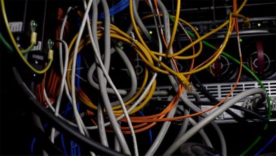
通信线缆:在以太网线缆等通信线缆中,需要多对双绞线进行数据传输。如果绞合不够紧或线缆屏蔽不良,则一对双绞线的信号会串扰到相邻的双绞线,导致数据损坏或信号质量降低。
高速数据传输:在HDMI或USB线缆等高速数据传输中,信号可能会因其高频率而相互干扰。这种干扰会产生串扰并降低信号质量。
射频系统:在射频(RF)系统中,相邻天线或RF传输线之间可能会发生串扰。这会导致信号干扰,降低系统的有效性。
SoC中的串扰
如果工程师在开发片上系统(SoC)架构时忽略串扰问题,那么他们就是在冒很大的风险。串扰会产生电子设计错误,从而导致上市延迟和成本超支。
识别EM串扰的挑战
为了帮助理解EM串扰分析的复杂性,工程师可以将该问题与电容耦合进行对比。
电容耦合的大小与距离呈反比关系。因此,工程师可以放心地忽略相距较远的信号线之间的电容耦合。与此相反,相对较远的信号之间的电感磁耦合是不容忽视的。

我们很难确定电磁串扰是否是问题的根源。
EM串扰更具挑战性。首先,问题的症状不会以单个指标的形式出现,比如时序故障。相反,串扰通常表现为某些关键性能标准的下降,这些标准因设计而异。因此,首要挑战就是识别串扰问题。
更复杂的情况是,串扰通常涉及数字、模拟和射频(RF)模块之间的不必要耦合。任何一个模块都可以成为干扰源或受干扰对象。
在不同的设计中,需要以不同的方式识别、调试和解决EM串扰。传统解决方案所包含的架构或软件,可用于防止能够导致问题产生的操作模式。然而,随着设计复杂性和速度的增长,这在成本上和技术上都难以为继。
EM串扰建模的挑战
为了进行准确的EM串扰建模,工程师需要分析和建模极其复杂的物理结构范围,其中包括:
- 目标网
- 导致串扰的周围结构
- 电源和接地布线层
- Bulk硅基板
- 封装层
- 键合/凸点焊盘
- 布线层
- 密封圈
- 金属填充
- 去耦电容器
由于需要包含所有组件,EM串扰建模可能十分复杂。
大多数结构的物理布局十分复杂,需要一个大网格来仿真电阻、电容、电感、耦合电容和互感。
增加串扰模型大小的第二个建模因素在于,工程师无法通过将焦点限制在设计中的小边界框来分析EM串扰。在评估电容耦合时,分析邻域受干扰信号的效果很好。然而,磁场可以沿着大环路传播,在受干扰信号附近形成干扰或环绕芯片的整个布局。
此外,很难限制由EM串扰工具生成的模型的大小,因为它需要包括可能导致串扰问题的所有网络以及可能影响电路性能的所有网络和结构。
为了对下游开发有好处,串扰模型必须:
- 在通用电路分析程序(SPICE)中快速计算
- 在SPICE环境中进行各种非线性仿真和噪声仿真
- 存在于跨越块边界或硅片边界的数据库中
考虑到串扰模型的典型尺寸和复杂性,这三个要求很难得到满足。
SoC对EM串扰分析的新需求
由于电子系统需要增加带宽和减小尺寸,EM串扰成为了工程师面临的一大难题。因为,这种情况下,高速电路和高带宽通道会相互接近。
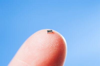
随着电子设备日益小型化,串扰将成为一个更大的问题。
此外,内部时钟频率(5-10GHz)的持续增加和数据速率(10Gbps以上)的增加也助推了串扰问题的出现。
简而言之,高速和小型电子设备会产生串扰;消费者需求正在助力形成SoC趋势,使得工程师无法再忽视寄生电感和电感耦合。
容易产生串扰的SoC架构
有许多架构和应用设计趋势会导致串扰。
例如,EM串扰与频率有关。然而,工程师无法只针对一个简单的相关频率来分析电磁串扰。
例如,具有快速上升和下降时间的时钟信号包含显著的谐波频率分量。因此,以10GHz运行的时钟包含了运行频率为50GHz的5次谐波频率分量。
同一系统上的多个以太网通道可能带来串扰危险。
然而,如果以25GHz片上时钟频率作为目标,工程师将不得不考虑如何安全地对属于微波频率的3次谐波进行建模。
EM串扰会影响信号幅度(即噪声水平)。因此,随着SoC应用中的低功耗趋势所导致的信号电压电平下降和噪声敏感度增加,串扰的影响将会进一步加剧。
此外,以太网、光纤通道和外部设备互连(PCI)也可能是串扰的来源。为了实现高数据速率,这些总线采用多个并行运行的串行通道。例如,一个100Gbps以太网可以使用10个以10Gbps的速度运行的通道。当如此多的高速串行通道存在于单个系统中,每个通道都可能成为潜在的干扰源或潜在的受干扰对象,这是真正的串扰危险。
其它可能增加EM串扰的架构趋势包括:
- 单个SoC上的高速模拟模块
- 类似于锁相环(PLL)和压控振荡器(VCO)
- 同一芯片上的多个高速时钟网络
- 不需要在高频下运行的时钟——在10GHz下运行的受干扰时钟可能会受到在2GHz下运行的干扰时钟的影响。
- 与高速数字模块相邻的RF或高速模拟模块
- 共享接地网络和硅基板不能用作接地。
- 硅基板仍然是模块之间的关键噪声传播通道。
- 代工厂插入的密封圈和切割线
- 具有较小信噪比裕度的低功耗设计
- 可通过串扰干扰设置的敏感控制/复位信号
- 集成扇出晶圆级封装技术
- 邻近的多个模块会增加EM串扰的可能性。
- 邻近的多个模块会增加EM串扰的可能性。
串扰解决方案
SoC集成将高速数字电路、模拟和射频模块紧密结合在一起,为这些组件内部和各个模块之间产生串扰创造了机会。
大多数电子设计自动化(EDA)工具都适用于特定的设计类型,例如数字、模拟或射频组件设计。然而,串扰不受这些界限的限制。
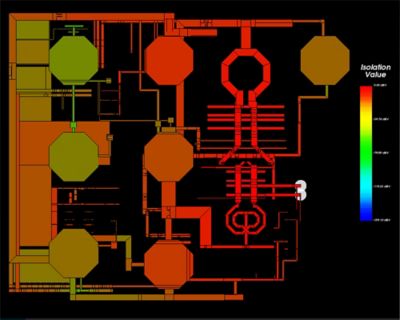
IC设计工程师应该能够在签核阶段预测耦合效应。使用Ansys RaptorH,IC设计人员能够准确预测电磁耦合效应,并轻松捕获设计层级中不同模块之间的未知串扰。
如欲了解有关串扰的更多信息,请阅读文章:优化高速串行链路的串扰。