-
-
Kostenlose Software für Studierende
Ansys unterstützt die nächste Generation von Ingenieur*innen
Studenten erhalten kostenlosen Zugang zu erstklassiger Simulationssoftware.
-
Verbinden Sie sich jetzt mit Ansys!
Gestalten Sie Ihre Zukunft
Stellen Sie eine Verbindung mit Ansys her, um zu erfahren, wie Simulation Ihren nächsten Durchbruch vorantreiben kann.
Kostenlose Demoversionen
Produkte & Dienstleistungen
Lernportal
Über das Unternehmen
Back
Produkte & Dienstleistungen
Back
Lernportal
Ansys unterstützt die nächste Generation von Ingenieur*innen
Studenten erhalten kostenlosen Zugang zu erstklassiger Simulationssoftware.
Back
Über das Unternehmen
Gestalten Sie Ihre Zukunft
Stellen Sie eine Verbindung mit Ansys her, um zu erfahren, wie Simulation Ihren nächsten Durchbruch vorantreiben kann.
Kostenlose Demoversionen
ANSYS BLOG
March 25, 2022
Simulating Just the Antenna is Not Enough: Analyze the Complete Antenna System with the Environment
Phased array antenna systems (PAAS) are antenna arrays that can change the shape and direction of a radiation pattern without physically moving the antenna. By placing the antennas in an array so the signals transmitted by individual antennas reinforce each other, engineers can achieve better gain, directivity, and performance in a particular direction.
PAAS are used everywhere from defense radar applications to commercial applications like 5G. They are often placed on moving platforms such as ships, airplanes, satellites, and trucks. However, the moving platform adds a degree of difficulty in aiming the radiation pattern in the desired direction. Other challenges arise from antenna-antenna interaction and antenna-platform interactions, so the placement of the antennas and materials used in building the platform can play a big role in the efficiency of a PAAS.
Designing these antenna arrays involves complex mathematics that are not easily solved by hand. Ansys HFSS full-field 3D electromagnetic simulation software is quite helpful in tackling these challenges quickly and easily.
Analyzing PAAS Interaction Variables
PAAS have multiple sub-systems like antenna arrays, transmit–receive modules (TRMs), array beamforming modules, and more. The active electronics behind the antenna array are enclosed in a metallic box or placed behind the ground plane of the antenna to avoid unwanted couplings.
The HFSS analysis involves studying the antenna unit cell, finite array, and placement effect on a large platform. In the example I'll focus on for this article, the large platform is the steel mast of a naval ship. The proximity of such a large mass of metal can have a major effect on the antennas and the radiation patterns emanating from them. Also, to keep the beam trained on the desired target as the ship moves, the angle of the transmitted beam will change often as the orientation of the ship changes. An effective PAAS must generate a satisfactory beam shape and range over all transmission angles.
HFSS combines various simulation techniques like 3D component-based finite array domain decomposition (FA-DDM), the method of moments (MOM), and shooting and bouncing rays (SBR) to analyze the beamform over a wide range of scan angles with great efficiency using minimal computational resources. We will analyze a 256-element finite antenna array comprising U-slot-based microstrip patch antennas (UMSA) with a wide bandwidth (BW) and wide half-power beam width (HPBW). Each UMSA is surrounded by a substrate-integrated waveguide (SIW) wall, which emulates a metallic cavity for mitigation of mutual coupling effects. These parameters are required to ensure the wide band and wide scan performance of a PAAS.
Determining Scan Angle Effects
We modeled a 64-element finite array using SIW-based UMSA as shown in Figure 1. We analyzed the structure for different frequency points and scan angles using high-performance computing (HPC) with 32 cores and 376 GB of RAM. Using the 3D component-based array simulation feature, HFSS solved a 64-element PAAS under 28 minutes using a 32-core machine with maximum utilization of 20 GB of RAM.
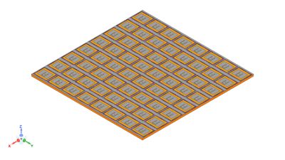
Figure 1. An 8x8 element array model based on UMSA
Figure 2 shows a comparison of the simulated and measured array pattern performance for the finite array image, demonstrating good agreement between HFSS simulations and physical measurments. Figure 3 shows the 3D radiation pattern plot. You can see a peak gain of 20 dBi and a peak sidelobe level better than -13 dB, with all the array elements being uniformily excited — a desired characteristic of an antenna array. The effect of scan angles can be estimated over frequency by post-processing the beamforming phase gradients using a built-in script in HFSS without redoing the simulations, which saves a lot of time.
These results show how HFSS is effective in simulating the beam pattern at a wide range of scanning angles so the antennas can track their target from a moving platform.
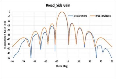
Figure 2. Antenna array radiation pattern at boresight
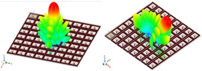
Figure 3. Post-processing of scan angles (0 deg, 45 deg)
Antenna-Platform Interaction
Now let’s consider the mounting platform: a naval ship with lots of other electronics and various structures onboard (see Figure 4).
The 256-element antenna is mounted on the ship’s mast, as highlighted in Figure 4. Figure 5 shows the antenna’s performance when installed on one of the faces of the mast with different steering angles (0 deg and 45 deg). The effect of the grating lobes with a larger scan angle is clear from the installed pattern. Figure 6 shows the antenna-to-antenna coupling when installed on the two faces of the mast. Figure 7 shows the simulated mutual coupling between the two antenna arrays estimated at different scan angles.
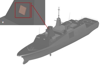
Figure 4. Mounting platform-a naval ship and 256 elements PAAS placement
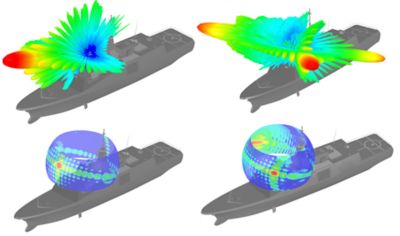
Figure 5. Installed antenna performance on the ship (0 deg and 45 deg)
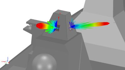
Figure 6. Antenna array-to-array coupling on the ship when mounted on the two faces
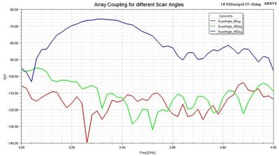
Figure 7. Mutual coupling between arrays estimated at different scan angles
These results show that HFSS provides distributed computing systems capable of solving complex phased array antenna platforms with minimal computational resources. It is imperative to analyze the effect of the complex platforms and surroundings on antenna performance to correctly predict its performance in practical applications.
Simulate with Confidence
We can simulate a complex phased array antenna system using Ansys HFSS in a reasonable amount of time and with low computation costs while considering the effects of complex excitations, environment (i.e., nearby antennas), and the platform on its performance. Simulation results of isolated antenna arrays are in close agreement with measured values, giving us more confidence in the Ansys simulations. This confidence helps to reduce the product development cycle. Different solvers work seamlessly together to extend the simulation for calculating array-to-array coupling and platform interactions on these electrically large models, which are difficult to measure in the real world.
Download the "How Complex Phased-array Antennas and Platforms Interact" application brief for more information.