-
-
Kostenlose Software für Studierende
Ansys unterstützt die nächste Generation von Ingenieur*innen
Studenten erhalten kostenlosen Zugang zu erstklassiger Simulationssoftware.
-
Verbinden Sie sich jetzt mit Ansys!
Gestalten Sie Ihre Zukunft
Stellen Sie eine Verbindung mit Ansys her, um zu erfahren, wie Simulation Ihren nächsten Durchbruch vorantreiben kann.
Länder und Regionen
Kostenlose Demoversionen
Produkte & Dienstleistungen
Lernportal
Über das Unternehmen
Back
Produkte & Dienstleistungen
Back
Lernportal
Ansys unterstützt die nächste Generation von Ingenieur*innen
Studenten erhalten kostenlosen Zugang zu erstklassiger Simulationssoftware.
Back
Über das Unternehmen
Gestalten Sie Ihre Zukunft
Stellen Sie eine Verbindung mit Ansys her, um zu erfahren, wie Simulation Ihren nächsten Durchbruch vorantreiben kann.
Kostenlose Demoversionen
ANSYS BLOG
March 6, 2023
From Concept to CubeSat, Part 1: Using Ansys Zemax Software to Develop a CubeSat System
In the aerospace industry, CubeSats have emerged as a low-cost, easily manufacturable solution for space-based optical systems. They offer a unique opportunity to develop a production line approach for a space-based products through constellations of smaller, more affordable systems.
Companies that manufacture CubeSat optical systems need an accurate and reliable method for developing an optical design, opto-mechanically packaging the system, and modeling structural and thermal impacts that the system will experience in orbit. This article series will explain the high-level development of a CubeSat system by using the Ansys software suites. We will illustrate how an integrated software toolset can streamline the design and analysis workflow.
For decades, optical systems have been developed for operation in low, medium, and high Earth orbit. For many optical systems, the packaging form factor and the opto-mechanics that stemmed from this form factor were designed on a system-by-system basis. CubeSats are a class of lightweight nanosatellite that can house optical systems for applications ranging from laser communications to Earth imaging. They are unique in that they use a standardized size and form factor.
For this blog series, the paper Optical Design of a Reflecting Telescope for CubeSat was used as a reference for developing the CubeSat optical design.1
In part one of this series, we will explain the standardized CubeSat form factor and cover the background details of building a CubeSat optical system in Ansys Zemax OpticStudio’s Sequential mode.
CubeSat Design Background
The CubeSat form factor is based on a standard that was originally developed as a collaboration effort between California Polytechnic State University and Stanford University’s Space Systems Development Laboratory (SSDL).2
The building blocks for standard CubeSat systems are in 1U — or one unit — cubes that measure 10 by 10 by 10 centimeters. While a 1U CubeSat is the base size, CubeSats can be built to a larger form factor through the addition of more 1U building blocks. The following graphic from NASA provides an illustration of standardized CubeSat sizes.3
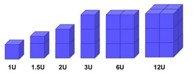
Figure 1. Standardized CubeSat sizes per NASA.
The CubeSat optical design referenced in this article series is an off-axis segmented, reflective telescope of the Ritchy-Chretian type. The design is meant to fit into a standardized 3U CubeSat form factor, or 10 by 10 by 30 centimeters. To maximize the field of view, the design consists of two hyperbolic mirrors that are rectangular in shape. The primary mirror and secondary mirrors have dimensions of 80 by 80 millimeters and 41 by 24 millimeters, respectively.
This design is meant to function as a high-resolution Earth imager in low Earth orbit (LEO) at 700 kilometers. The design has an effective focal length of 685 millimeters and is designed to work in the visible spectrum. At the primary wavelength, the design has a ground resolving distance of 9.11 millimeters which enables system engineers to image two distinct objects that are at least that distance apart. The ground resolving distance can be calculated with the following equation:

As designed in OpticStudio, the CubeSat is assumed to operate at room temperature, but in orbit, the optics are expected to perform at an operating temperature of 15 degrees Celsius, plus or minus 3 degrees. The detector for this system has an active array of 1280 by 800 pixels, with each pixel being 3 by 3 micrometers (μm). This allows for a total imaging area of 3.84 by 2.4 millimeters.
The main performance metrics for this design are to achieve a diffraction limited spot size at every field point and to achieve a modulation transfer function (MTF) of 0.25 at 80 cycles per millimeter. These metrics were referenced from the same paper on which this design was based.
Designing the Optics in Sequential Mode
Based off the design prescription, global system parameters were set in the System Explorer, and the optics were inserted with the proper specifications in the lens data editor.
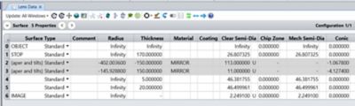
Figure 2. Initial optical prescription.
Even though the final design contains mirrors with rectangular apertures, the first stage of the design had the mirrors retain a circular shape. Retaining the circular shape of the mirrors prevents the optimization from being over constrained at the start of the process. To position both mirrors off-axis, the two mirrors were decentered with respect to the global optical axis. Because of this, even though the rays are able to focus on the correct location, the image plane is offset from the rays. At this stage, the image plane is floating near the top of the primary mirror and is aligned with the global optical axis of the coordinate system.
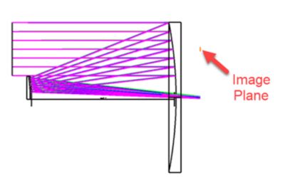
Figure 3. Incorrect image plane location.
To be brought to the correct location, the image plane needs to be decentered with a coordinate break. Using a chief ray solve on the Decenter Y measurement, the image surface is aligned with the real chief ray. The image plane is now properly positioned.
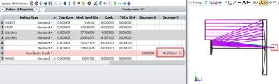
Figure 4: Chief ray solve.
With the basic layout finalized, optimization can now begin. To preserve the system’s F/# of 12.455, an effective focal length (EFFL) operand was used in the merit function to target 685 millimeter in conjunction with a root mean square (RMS) spot size default merit function. Multiple optimization runs were conducted in which the radii of each surface and the thicknesses were iteratively optimized.
Because space is limited in a CubeSat system, it is critical to pay close attention to the total track length of the system and areas in which to vignette the rays. The total track length for this design is 19.5 centimeters with 2Us of space devoted to the optics. The remaining 1U of space is devoted to system electronics. The total track length can be monitored via the merit function by using a thickness (TTHI) operand between the STOP and the image plane.
After verifying the design would fit within the size constraints of a 3U CubeSat and ensuring that performance was as expected after optimization, the mirrors were adjusted to be rectangular. They were adjusted to the proper shape by applying rectangular apertures.
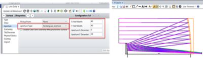
Figure 5. Rectangular aperture.
After adjusting the aperture settings, it was discovered that the secondary mirror was partially clipping the incoming ray bundle. With further decentering of the secondary mirror aperture, the results were favorable. After adjustment, the footprint diagram was used to verify that the full beam footprint reaches every critical surface of the system.
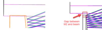
Figure 6. Clipping of the beam.
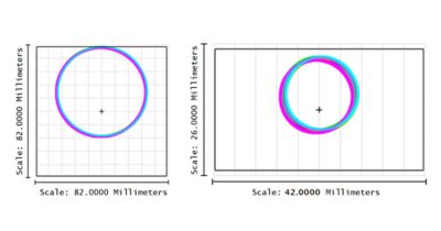
Figure 7. Footprint diagram of mirror one (left) and mirror two (right).
At this stage, the design has been laid out in OpticStudio, optimized, and adjusted such that it fits within a 3U CubeSat form factor.
The spot size is diffraction limited at all field points, and the MTF meets the specification of 0.25 at 80 cycles per millimeter. With the optical performance meeting requirements, the mirror thicknesses were increased as a final update to the base model. If the mirrors remain as thin as 5 millimeters, this could cause issues down the road when applying a temperature condition across the optics. In the Draw tab of the Object Properties menu, the thickness was adjusted to 18 millimeters and 15 millimeters for the primary and secondary mirrors, respectively.
References
- Jin H, Lim J, Kim Y, Kim S. Optical Design of a Reflecting Telescope for CubeSat. J Opt Soc Korea. 2013;17(6):533-537. doi:10.3807/josk.2013.17.6.533
- About — CubeSat. CubeSat. https://www.cubesat.org/about. Accessed February 13, 2022.
- Mabrouk E. Cubesat Form Factors.; 2015. https://www.nasa.gov/content/what-are-smallsats-and-cubesats. Accessed February 13, 2022.