-
-
Access Free Student Software
Ansys empowers the next generation of engineers
Students get free access to world-class simulation software.
-
Connect with Ansys Now!
Design your future
Connect with Ansys to explore how simulation can power your next breakthrough.
Countries & Regions
Free Trials
Products & Services
Learn
About
Back
Products & Services
Back
Learn
Ansys empowers the next generation of engineers
Students get free access to world-class simulation software.
Back
About
Design your future
Connect with Ansys to explore how simulation can power your next breakthrough.
Free Trials
TOPIC DETAILS
What is an Analog Integrated Circuit (IC) and How is it Designed?
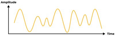
What is an Analog Signal?
An analog signal is a continuous waveform in which a fluctuating attribute such as voltage or pressure corresponds to another time-dependent variable. In other words, one variable is an analog of the other. The signal passes from one value to another and passes through all the intermediate values, from zero to full amplitude.
What is an Analog IC?
Analog integrated circuits (IC) are electronic circuits that process analog signals. They are the basic parts of most electronic devices and manipulate signals such as audio, temperature, light, and voltage. Unlike digital ICs, which process on/off signals, analog ICs work with a signal's entire range of values.
Analog ICs are responsible for functions like amplification, filtering, mixing, modulation, and demodulation. They are widely used in applications where accurate and efficient signal processing is essential.
Examples and Applications of Analog ICs
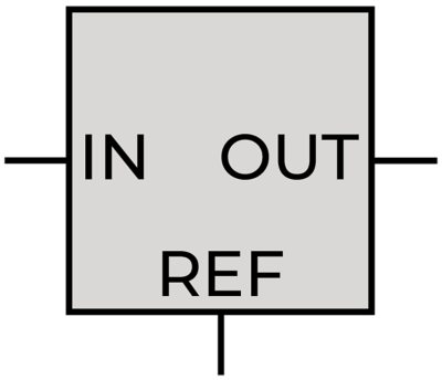
Voltage and current regulators: It is commonly used in power circuits where the output should remain constant irrespective of varying input voltage. The regulator IC ensures constant output. Voltage regulators are commonly used in all power supply systems.
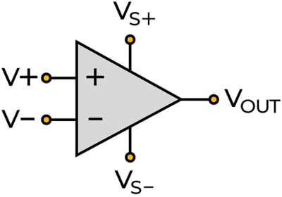
Operational Amplifiers (op-amp): Op-amps are used to amplify the input signal to a higher level as required by the load. Op-amps can also filter unwanted signals. The most common application of op-amp ICs is audio amplifiers.
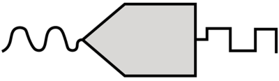
Data converter ICs: These ICs are used to convert analog signals into digital signals and are known as Analog-digital-converters (ADCs). These ICs are used where the input signal is continuous (sound, heat, etc.) and has to be converted into a digital stream for processing. The common application is radio.

Audio amplifiers: Audio amplifier ICs are used in radiofrequency applications where the received analog signal is very weak. They accept the low input frequency and raise it to a higher level that is required by the circuit. These chips are commonly used in communication systems.
Analog IC vs Digital IC Comparison
- Signal Representation: Analog ICs work with continuous signals where the value changes over time. On the other hand, digital ICs use discrete signals which are represented in binary form (0 or 1).
- Circuit components: Analog circuits use resistors, inductors, capacitors etc. whereas the main components of digital circuits are logic gates.
- Precision and Accuracy: Analog ICs are susceptible to noise and signal degradation, which can affect their precision. Analog systems are also susceptible to environmental factors like temperature changes. Whereas digital ICs offer high precision and accuracy due to the discrete nature of digital signals. Digital systems are more resistant to noise and external interference.
- Complexity and Functionality: Designing complex analog circuits can be challenging due to the continuous variation in the input signal. These ICs are commonly used in audio amplifiers, sensors, and analog filters. Digital ICs allow for complex logic operations, making them suitable for microcontrollers, memory storage, and digital signal processing tasks.
- Power Efficiency: Analog circuits consume more power but can be more power-efficient than digital circuits. Digital circuits can be power-efficient during periods of low activity (when transistors are mostly in standby mode), they consume more power during switching and active computation.
How to Design Analog ICs?
The design process of analog ICs involves multiple stages and a deep understanding of electronics and semiconductors. An analog chip design process must consider implementation challenges early in the design cycle and use simulation software to predict the behavior. The steps to design it are as follows:
Conceptualization and Specifications: The process begins by defining the purpose and functionality of the IC. Engineers work closely with clients and domain experts to outline the circuit's performance requirements, power constraints, operating conditions, and target applications.
Schematic Design: Create a high-level circuit diagram of the circuit using transistors, resistors, capacitors etc. This blueprint outlines the interconnections between various components and their functions.
Verification: Before moving to physical fabrication, engineers must use spice simulation software to simulate the circuit's behavior. This step helps to identify potential issues, refine the design, and optimize performance.
Layout Design: After the schematic, engineers translate it into a physical layout using Computer-Aided Design (CAD) tools. The layout involves placement components, designing interconnections, and most importantly design integrity. To create a robust and reliable design, engineers consider factors like parasitic effects, electromagnetic interference (EMI), heat dissipation, electrostatic discharge (ESD), electromigration (EM), IR drop etc. This is the most time-consuming step where designers must investigate the design thoroughly before moving onto the next step.
Fabrication: It involves building up layers of materials to create the semiconductor devices and interconnects. The final product undergoes QA before releasing to the market.
Analog and Mixed Signal IC Simulation
Signoff analysis is a proactive measure to mitigate potential project risks, effectively averting costly errors during silicon production. Utilizing precise multiphysics simulations enhances design performance by removing unnecessary safety margins, resulting in improved correlation with silicon outcomes. Ensuring power and signal integrity earlier in IP design cycle effectively reduces the turnaround time and enables design engineers to signoff confidently.
Learn more about power noise and reliability signoff in this white paper: Analog and Mixed Signal Workflows for Power and Reliability Signoff for SerDes IP and PMIC
Related Resources
Let’s Get Started
If you're facing engineering challenges, our team is here to assist. With a wealth of experience and a commitment to innovation, we invite you to reach out to us. Let's collaborate to turn your engineering obstacles into opportunities for growth and success. Contact us today to start the conversation.