Synopsys and Ansys power the future of innovation—connecting silicon to systems.
-
-
学生向け無料ソフトウェアにアクセス
Ansysは次世代の技術者を支援します
学生は、世界クラスのシミュレーションソフトウェアに無料でアクセスできます。
-
今すぐAnsysに接続!
未来をデザインする
Ansysに接続して、シミュレーションが次のブレークスルーにどのように貢献できるかを確認してください。
無料トライアル
製品およびサービス
リソースとトレーニング
当社について
Back
製品およびサービス
トピックの詳細
マルチボディダイナミクスとは
ほとんどの機械は、複数の部品で構成されています。ロボット、産業機器、自動車用サスペンション、医療機器などの製品は、ジョイントによって接続された構造をベースとしており、モータやアクチュエータで駆動します。マルチボディダイナミクス(MBD: Multibody Dynamics)は、運動量、接触、加速度を考慮して、相互接続された部品で構成される機械システムの動的挙動をモデル化する数値シミュレーションのサブセットです。
マルチボディシステムは複雑であり、システムを構成するコンポーネントは複雑な方法で相互に作用するため、エンジニアは製品開発および製品ライフサイクル管理プロセスにマルチボディダイナミクスシミュレーションを導入しています。たとえば、産業機械のモータサイズを決定するには、ギアボックスの損失、ジョイント部の摩擦、部品に作用する外力、コンポーネントの運動量に基づいて必要なトルクを計算する必要があります。
MBDモデルはほぼリアルタイムで解析されるため、有限要素法解析(FEA)モデルなどの忠実度の高い完全表現よりもはるかに効率的です。同じ業界内で使用されるメカニズムは類似していることが多いため、多くのMBDソフトウェアパッケージには、モデルの作成を高速化し、設計プロセスの早い段階で製品に関する正確で実用的な情報を取得するのに役立つ、応用分野に固有のツールも含まれています。
マルチボディダイナミクスシミュレーションに関連する重要な定義
MBDシミュレーションを導入するための具体的なツールや推奨事項を検討する前に、運動の支配方程式、物理特性、MBDモデルの内容など、マルチボディダイナミクスにおける基本的な定義を理解しておくとよいでしょう。
運動方程式
MBDモデルは、ニュートンの運動方程式であるF = ma(力 = 質量×加速度)の数学的表現を、システム内の各ボディの挙動を考慮するために時刻歴応答の形式に変換したものです。
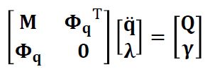
M = システムの質量マトリクス
q = 一般化座標(システムの位置)
\( \Phi_{q} \) = システムの拘束をシステムの一般化座標に関連付ける拘束ヤコビ行列
\( \Phi_{\tau}^{q} \) = 拘束ヤコビ行列の転置
未知ベクトル(ソルバーで計算する値):
q̈ = システム内のボディの一般化加速度
\( \lambda \) = ラグランジュ乗数(拘束力を表すベクトル)。これらはボディ間の接続にかかる未知の力とトルクです。
力および拘束ベクトル(右辺ベクトル):
Q = 加えられた一般化力(重力、バネ力、ダンパー力、アクチュエータ力、モータ力、コリオリ力、遠心力を含む)
\( \Upsilon \) = 速度および固定位置を含む加速度拘束
マルチボディダイナミクスシミュレーションの産業用途
多くの業界では、相互に相対的に移動し、ボディ間で力を伝達するコンポーネントで構成されたマルチボディシステムの製品が製造されています。以下に、機械エンジニアがMBDシミュレーションを使用して設計および保守する製品のシステムダイナミクスを理解するための5つの実例を示します。
産業機器
製造機械や材料加工機械の多くは複雑なメカニズムによって駆動しているため、それらを設計する機械エンジニアはマルチボディダイナミクスシミュレーションを活用しています。エンジニアは、MBDモデルを使用して機能の仮想プロトタイピングを行います。また、これらのモデルを使用して、部品間で不要な接触が生じないようにし、モータやアクチュエータのサイズを調整して、コンポーネントに繰り返し加えられる荷重を計算して疲労を推定します。さらに、モデルを使用してシステムの効率を最適化し、入力パラメータとジオメトリを調整して、スループットを向上させます。制御ソフトウェアをMBDモデルに接続して、仮想環境でシステム全体のテストを実行することもできます。
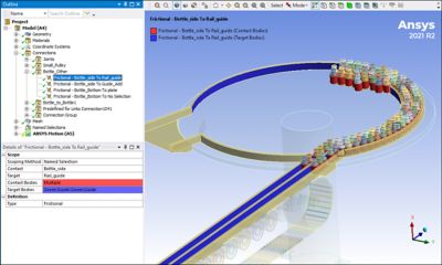
マルチボディダイナミクスシミュレーションソフトウェアのAnsys Motionでモデル化されたボトル選別システムの例
自動車用サスペンション
自動車には、MBDシミュレーションの恩恵を受けるさまざまなメカニズムが搭載されています。実際に、マルチボディシミュレーションアプローチを初めて採用したのも自動車エンジニアでした。自動車のサスペンションは、粗い路面を走行する際の動荷重を吸収して滑らかにするように設計されたバネやダンパーを含む複雑な連動部を備えており、マルチボディダイナミクスに最適です。このタイプのシミュレーションは、ドライバーや乗客に快適な体験をもたらすための自動車の騒音、振動、ハーシュネス(NVH)研究に不可欠な要素となっています。
宇宙機
MBDシミュレーションは、宇宙機を設計する航空宇宙エンジニアにとって重要なツールです。このツールなしに、無重力下でのシステムの動きや荷重を地球上で簡単にテストすることはできません。MBDシミュレーションは、ロケットモータの推力方向を調整するジンバル、ソーラーパネルの展開メカニズム、液体エンジンや冷却システムで使用されるモータやバルブなどの開発に導入されています。
ロボティクス
ロボットは、マルチボディダイナミックシステムの最も直接的な実世界表現と言えるでしょう。ロボットは、ジョイントで接続された剛体で構成されており、モータやリニアアクチュエータで駆動します。多くのロボットプログラミングシステムには、プログラミングワークフローの一環として正確なシミュレーションを実行するためにMBDソルバーが組み込まれています。産業機器と同様に、マルチボディダイナミクスシミュレーションの目的は、衝突の可能性を検出し、荷重や疲労寿命を計算して、速度を最適化することです。
マルチボディダイナミクスシミュレーションソフトウェアのAnsys Motionでモデル化されたロボットのアニメーション
生体力学
私たちの身体も、ダイナミックマルチボディシステムの一例です。人体の筋肉は、関節を中心として骨を動かし、1つの軸(指関節)、2つの軸(手首)、または3つの軸(腰)を中心に回転させる腱を引っ張るアクチュエータとして機能します。バイオメディカルエンジニアは、MBDシミュレーションを使用して、アスリートのパフォーマンス、人工関節の設計、理学療法のための医療機器の設計を最適化したり、骨折や捻挫からの回復を促すために身体の部位を固定したりします。
マルチボディダイナミクスシミュレーションの物理特性
以下に、マルチボディダイナミクスモデルの物理特性を説明する際に広く使用されている用語を挙げます。
- 自由度: モデル内の任意点の位置と方向。3次元空間における剛体は、3つの軸(x、y、z)に沿った並進3方向と3つの軸(RotX、RotY、RotZ)を中心とした回転3方向の計6自由度を持ちます。
- 運動学: 物体に働く力を考慮せず(質量と運動量を考慮せず)、線形運動や回転運動を扱う分野。
- 動力学(ダイナミクス): 物体に働く力を考慮して(質量と運動量を考慮して)、時間経過に伴う運動を扱う分野。
- 質量: 線形加速度に対する物体の抵抗。
- 慣性モーメント: 角加速度に対する物体の抵抗。
- 重心: 物体内の質量の平均位置。これは、すべての質量が集中する単一点を表します。
- 質量特性: ボディの質量、慣性モーメント、および重心。
- 動的な力: システム内の物体に作用する外力および内力。動的な力の例として、重力、バネ力、ダンパー力、アクチュエータ力、モータ力、摩擦力、コリオリ力、遠心力があります。減衰やバネの場合と同様に、力は物体の位置や速度に依存するケースもあります。
- 制約: 自由度の位置、速度、または加速度について定義された値。
- 拘束方程式: 2つ以上の自由度の位置、速度、または加速度の関係を記述した定式化。
マルチボディダイナミクスシミュレーションモデリングの用語
MBDモデルでは、以下の用語を用いてさまざまな部分を表現します。
- 剛体: 荷重が適用されても変形しない理想化された物体。数学的に見た場合、剛体では2点間の距離が変化しないと言えます。
- 弾性体: 荷重が適用されると変形する物体。MBDツールでは、この柔軟性を簡略化された方法または詳細な方法で表現するために、いくつかの異なるアルゴリズムを使用します。
- 接続:モデル内のボディ間の相対運動(ジョイント)または力(制御デバイス)を定義する2つの物体間の関係。
- ジョイント:自由度間の拘束を指定する2つの物体間の接続。たとえば、回転ジョイントでは、単一軸を中心とした回転が可能であるが、相対並進はなく、他の軸を中心とした回転もありません。
- 制御デバイス: 2つのボディ間またはボディとグランドの間の力を定義するアルゴリズム。制御デバイスには、モータ、アクチュエータ、ダンパー、ギア、バネなどがあります。
- 境界条件: 位置、速度、または加速度の形で定義された運動。
- ノード:ソルバーで接続、力、変位、回転の方程式と解が計算されるモデル内の任意点。
- 荷重: 物体に作用する内力、外力、またはトルク。
- 接触: 2つのボディが接触したときの相互作用と、それらの間の接触力の伝達。動解析では、接触の指定により、あるボディの別のボディへの貫通が阻止されます。
- センサー: モデル内の物理特性を測定してレポートする、モデル内のシミュレーションされるデバイス。例として、2つの節点間の距離、ジョイントにおける反力とトルク、ボディの線形および回転位置、速度、加速度などがあります。センサーは、シミュレーション中に、荷重を計算するために制御デバイスが使用する値を計算するためにも使用されます。
マルチボディダイナミクスシミュレーションを導入して設計を推進するための推奨事項
メカニズムが含まれるシステムは、設計プロセスでのマルチボディダイナミクスシミュレーションの導入による恩恵を受けることができます。それは、あらゆるものが適切に動くことを確認するための単純な運動解析や、接触、非線形バネ、複雑なステッピングモータ制御ソフトウェアを使用した複雑な非線形動解析でも同じです。
MBDモデリングを成功させるための最も重要な推奨事項は、マルチボディダイナミクスシミュレーションソフトウェアであるAnsys Motionなど、ロバストで正確かつ高速な汎用MBDツールを選択することです。CADと統合でき、高度な機能を提供する使いやすいツールを選択しても、製品シミュレーション機能は制限されません。
また、モデルの計画に時間をかけることも重要です。以下に、価値の高いロバストなMBDシミュレーションを作成するために必要なものを文書化する上で適切な開始点となる手順を示します。
- MBDモデルの目標を決定します。
- アセンブリを詳細に設定します。
- 剛体と弾性体を特定します。
- 弾性体が表現すべき手法を決定します。
- ジョイントと制御デバイスを定義します。
- 解析中および解析後に情報を取得するためのセンサーを配置します。
選択したMBDシミュレーションソフトウェアで、モデルの設定とポストプロセスを大幅に簡易化するアプリケーション固有のワークフローが提供されるかどうかを確認することも推奨されます。たとえば、Ansys Motionには、チェーン、ベルト、トラックをモデリングするためのDrivetrainツールキット、Carツールキット、Linksツールキットなどのツールが含まれています。
MBDモデルは、MATLAB/Simulinkコントロールモデルに接続したり、デジタルツインソフトウェアのAnsys TwinAIで次数低減モデルを作成したりすることで、モデルベースシステムズエンジニアリングソフトウェアであるAnsys ModelCenterなどのツールで、システムレベルのシミュレーションをサポートすることもできます。
関連リソース
さあ、始めましょう
エンジニアリング課題に直面している場合は、当社のチームが支援します。豊富な経験と革新へのコミットメントを持つ当社に、ぜひご連絡ください。協力して、エンジニアリングの障害を成長と成功の機会に変えましょう。ぜひ今すぐお問い合わせください。