-
-
学生向け無料ソフトウェアにアクセス
Ansysは次世代の技術者を支援します
学生は、世界クラスのシミュレーションソフトウェアに無料でアクセスできます。
-
今すぐAnsysに接続!
未来をデザインする
Ansysに接続して、シミュレーションが次のブレークスルーにどのように貢献できるかを確認してください。
国および地域
無料トライアル
製品およびサービス
リソースとトレーニング
当社について
Back
製品およびサービス
ANSYS BLOG
July 27, 2022
Ansys Maxwell 2022 R2 Features Co-simulation With Ansys Motion
Learn about the new magnetic latching analysis workflow with multibody dynamics
On modern portable devices, permanent magnets often hold things together — literally. Without them, the detachable keyboard would never reattach, the stylus pen that comes with a tablet would roll helplessly away, and the wireless phone charging pad would be nothing more than a glorified mouse pad.
For engineers designing permanent magnet latching mechanisms, the magnetic configuration must provide an appropriate latching capability. The goal is to create the right force in the right place — enough for a strong hold but without the risk of magnets destroying adjacent metal or plastic materials, or even themselves since they are built from brittle materials.
Figure 1. Animation showing the latching mechanism in an actual product vs. a simulation
What’s needed is a normal seal, a safe configuration, and the right dynamic interaction between the user and the equipment itself. Designing something that meets those objectives requires consideration of complex dependencies, including the magnets’ material characteristics, dimensions, position, and installation, and how to isolate them from printed circuit board (PCB) components to avoid interference and distortion. Even the electronic device’s eventual operating conditions, including temperature profile, come into play, especially to avoid demagnetization.
The new Magnetic Latching Analysis Workflow with Multibody Dynamics in Ansys Maxwell 2022 R2 simplifies the process. Through co-simulation with Ansys Motion, which enables fast and accurate analysis of both rigid and flexible bodies, Maxwell now provides a comprehensive magnetic and kinematic solution for magnetic latch design.

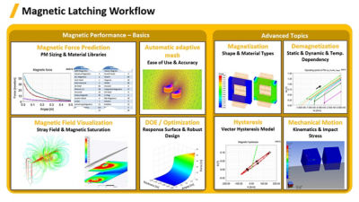
Figure 2. Modeling permanent magnets and magnetic latches with a comprehensive Ansys solution
The Magnetic Latching Analysis Workflow with Multibody Dynamics addresses engineering challenges more completely than ever.
- Electromagnetic coupling with kinematics ensures full degrees of freedom control of permanent magnets’ motion.
- The advanced design of permanent magnets is made possible through:
- Airgap, shape, sizing, and material studies
- Saturation and stray flux effects
- Magnetization and irreversible demagnetization with temperature dependency
- Vector hysteresis modeling
- Easy-to-use automated adaptive meshing provides an accurate solution.
- 2022 R2 contains scalable and customizable workflows.
- Co-simulation saves setup and calculation time.
More Back and Forth
Integrating Maxwell and Motion is nothing new, but until now, only one-way coupling was possible. Maxwell could export force calculations into Motion, but there was no way for Motion to send its calculations back to Maxwell.
The Magnetic Latching Analysis Workflow with Multibody Dynamics provides complete connectivity between the two, consolidating the benefits of a full kinematic rigid body solver and an electromagnetic solver in a single design space.
Now, the general workflow starts with Motion defining the kinematics transient design and launching the coupling with Maxwell’s magnetostatic solution. During transient analysis, Motion transfers information about an object’s position (full degrees of freedom) while Maxwell assigns the position coordinates to selected objects, computes the magnetic forces and corresponding torque, and then transfers this information back to Motion, where the transient simulation continues. Motion controls the electromagnetic solution while performing kinematics and impact analysis in greater detail.
What Else is New?
Understanding the Losses: Core Loss-dependent ROM for Induction Machine
Creating a reduced order model (ROM) for an induction machine is a tough assignment for electrical machine designers and systems engineers who are evaluating the impact of component design on the entire drive system. However, it’s critical to speeding the development process, lowering its cost, and ensuring better product performance.
Figure 3. Ansys Maxwell generates the reduced-order model (ROM) for the induction machine, which Ansys Twin Builder is using as component of a larger drive system simulation
Given the complexity of the geometries, material characteristics, excitations, and other variables, integrating high-fidelity 2D or 3D finite element analysis (FEA) models in a single system simulation — where all components are interconnected and electronically controlled — is prohibitive. Instead, to simulate the entire system or subsystem, the engineer must extract behavior information, including losses affecting performance, from the FEA and create equivalent models to use in larger schematics. The challenge is to realize the time-domain circuit based on frequency-dependent core-loss parameters identified in the frequency domain of an FEA simulation.
This release of Maxwell increases induction machine ROM accuracy at the system integration level by incorporating loss dependency. Maxwell extracts the FEA parameters to generate an equivalent model in Ansys Twin Builder, which speeds up system simulation while preserving FEA accuracy.
Driven to Improve: Skew Modeling to a New Paradigm
Designing skewed electric motors for automotive applications requires maximizing the torque profile over a wide range of speeds while making the torque as smooth as possible.
New capabilities in Maxwell 2022 R2 make achieving those twin goals easier than ever.
ROM of a 2D Skew Design
As far as electrical machine designs are concerned, engineers often perform detailed FEA on a 2D cross-section of a 3D geometry. However, because there are limits on how well a 2D cross-section can account for 3D effects, it doesn’t provide the most precise simulation, especially when skew topologies are being employed to design stators or rotors. To address this challenge, Maxwell provides multi-slice technology to account for skew 3D effects on a 2D cross-section design. In 2022 R2, Maxwell provides a ROM technique based on multi-slice technology for extracting an equivalent circuit model of a 2D skew design. This enables designers to take advantage of 2D FEA speed while preserving the accuracy of 3D FEA simulation.

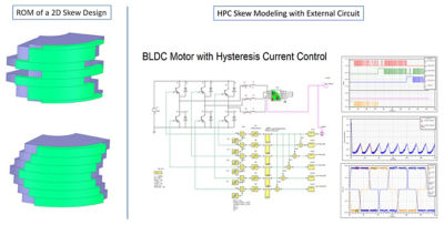
Figure 4. On the left: Ansys Maxwell now has a mathematical algorithm (multi-slice technology) that enables designers to take advantage of 2D finite element analysis (FEA) speeds while preserving the accuracy of 3D FEA simulation. On the right: Multi-slice technology introduced by Maxwell 2D solver has been enhanced by a high-performance computing (HPC) option to distribute in parallel every computed slice over MPI (message-passing interface) technique.
HPC Skew Modeling With External Circuit
The new high-performance computing (HPC) option in Maxwell distributes every computed slice based on the message passing interface (MPI) technique, speeding the entire 2D FEA simulation by solving the skew transient model across multiple cores. The HPC option supports external circuit co-simulation with MPI-based skew modeling in Maxwell transient design.
Additional capabilities in 2022 R2 include:
- Robust nonlinear characteristics for a 3D electric transient solution that addresses the design challenges associated with semiconductor and high-voltage application designs.
- Thin layer insulation boundary conditions for its 3D AC conduction solver to enhance total time computation by reducing the number of finite elements required to mesh tiny objects used as insulators.
- Maxwell extends its rigid motion capabilities through its magnetic transient solver by using translation motion with moving objects touching stationary objects.
Watch the Webinar
Ready to learn how Ansys Maxwell 2022 R2 updates and enhancements can make magnetic latching analysis and other challenges easier and less time-consuming? Watch the webinar: What’s New in Ansys Maxwell.