-
-
学生向け無料ソフトウェアにアクセス
Ansysは次世代の技術者を支援します
学生は、世界クラスのシミュレーションソフトウェアに無料でアクセスできます。
-
今すぐAnsysに接続!
未来をデザインする
Ansysに接続して、シミュレーションが次のブレークスルーにどのように貢献できるかを確認してください。
無料トライアル
製品およびサービス
リソースとトレーニング
当社について
Back
製品およびサービス
ANSYS BLOG
October 27, 2021
Reach Optimum Design and Reduce Charging Time with Ansys’ Wireless Charging System Analysis
Inductive-based wireless charging systems are widely used in applications such as medical devices, consumer electronics, and electric vehicles. This technology provides great convenience to users because the power is transferred without any electrical contact.
Primary design challenges and goals for wireless charging systems include maximizing efficiency and increasing power density to reduce device charging time. Additional goals include optimizing thermal performance and considering the effects of various shielding topologies.
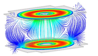
Fig. 1. H field streamline
The controls, power electronics, and load circuits are also an important part of system performance. Today, simulation technology enables 3D physics modeling of the electromagnetic (EM) and thermal performance of the transmitter and receiver coils as well as the magnetic flux concentrators and shielding used for the application. Integrating this and more, Ansys offers an end-to-end wireless power supply system analysis with physics-based circuit and system modeling to achieve such goals.
For EM analysis of wireless charging systems, Ansys Maxwell’s finite element method (FEM) technique uses automatic adaptive meshing technology to predict coil coupling inductance for any sized coil under any misalignment condition. This meshing technology ensures the models are using an appropriate, efficient, and accurate mesh for the physics being solved as shown in Fig. 2. It also accounts for the effects of permanent magnets, magnetic materials, and losses due to eddy effects in conductive shields or nearby objects unprotected from stray fields that may exist outside the device footprint.
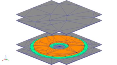
Fig. 2. (a) Initial mesh plot
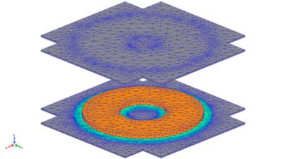
Fig. 2. (b) adaptively refined mesh plot
Fig. 3. B field contour on cross section under misalignment
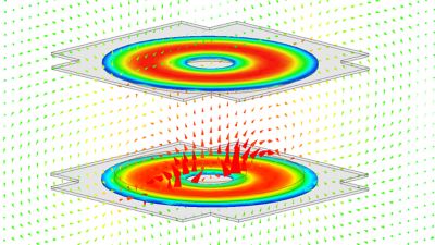
Fig. 4. B field contour in core and H field vector on cross section plane
Though permanent magnets are often used in wireless charging devices for alignment, they can generate strong static magnetic fields that can saturate the ferrite core and create eddy effects when coil currents generate time-varying magnetic fields sinusoidally. In this case, resistor–inductor (RL) parameters would be affected and, if not accounted for, influence the accuracy of efficiency analysis.
Ansys provides two solutions for modeling wireless charging coils with permanent magnets. The first solution is a transient solver approach, which provides magnetic field distribution by combining the direct current (DC) field emanating from the permanent magnet with the time-varying field generating from the receiver and transmitter coils. The second solution is a permeability link method, which is the preferred workflow to run a system-level analysis by integrating RL parameters from the wireless charging system with additional subsystems, such as an inverter or battery.
For consumer electronics, the most acknowledged in the industry is Qi standard, which was developed by the Wireless Power Consortium and best known for helping to standardize wireless charging systems. To provide a convenient and accurate modeling solution for customers with different levels of technical backgrounds in wireless charging, Ansys Maxwell 2021 R2 features the 3D Component (3DC) library of Qi Wireless Power Transfer System, in which 54 reference designs are created for power transmitters and receivers.
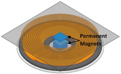
Fig. 5. Wireless charging with permanent magnets
The Qi standard 3DC workflow in Ansys Maxwell is straightforward. Geometry, excitations, solution setup, and parameters are already setup for each component. The model can be easily built by dragging and dropping the receiver and transmitter components into the Maxwell design. The design is then ready to be analyzed with a few basic model setup steps.
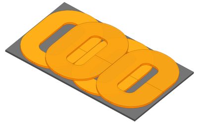
Fig. 6. Qi standard power transmitter with rectangular coils
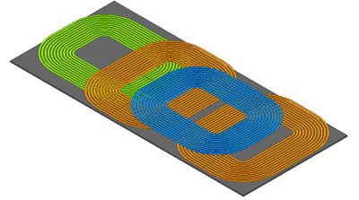
Fig. 7. Qi standard power transmitter with multiple coils for extended power profile
Transmitting power, even wirelessly, will generate heat in transmitting and receiving coils, as well as in the magnetic and conductive parts of the wireless charging devices. Heat may also generate unintentionally in nearby parts. To meet or beat temperature limits, it is imperative to predict where heat originates and plan for thermal performance under different charging loads to achieve optimum design. Within the Ansys Electronics Desktop, you can integrate Ansys Maxwell’s EM analysis — including EM losses in coils (solid loss, litz winding loss, etc), cores (hysteresis loss), shields, and permanent magnets (induced eddy current loss) — into Ansys Icepak to analyze thermal performance.
Fig. 8 Hysteresis loss distribution in cores
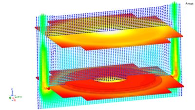
Fig. 9. Temperature plot with air flow
Wireless charging system efficiency depends on many factors, including coil quality factors, losses, and control strategies. Enabling frequency-dependent magnetic finite element analysis (FEA) reduced order models (ROMs) for circuit and system simulation allows for the accurate prediction of system efficiency in the time and frequency domain (Figure 10 and 11). It also enables the evaluation of different power electronics topologies for sensing and controls.
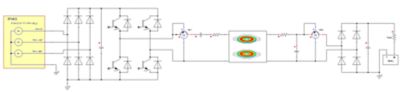
Fig. 10. Wireless charging system with ROM generated from Maxwell
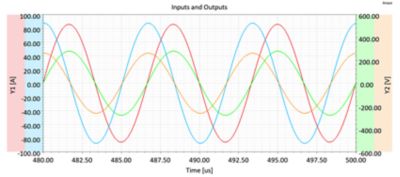
Fig. 11. Input and output currents and voltages
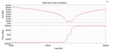
Fig. 12. Bode plot of input impedance
To further enhance wireless charging design and achieve peak power and efficiency, Ansys optiSLang can be coupled with Ansys Maxwell to identify the most important design variables with sensitivity analysis, obtain the best possible Metamodel Optimization Prognosis (MOP) with Coefficients of Prognosis (CoP), and run optimization algorithms based on the objective functions.
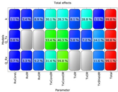
Fig. 13. CoP matrix of wireless charging design parameters in Ansys optiSLang
Ansys’ simulation solutions integrate magnetic, thermal, and electrical system performance and enable optimum design of wireless chargers for electric vehicles, consumer electronic and medical devices. This workflow allows engineers to achieve new power levels, higher efficiency, and reduce product cost of new or existing designs. To learn how to model and analyze inductive-based wireless charging systems using Ansys Maxwell to reach optimum design, request the on-demand webinar Wireless Charging Systems – Create Better Designs Through Simulation.