Synopsys and Ansys power the future of innovation—connecting silicon to systems.
-
-
Software gratuito per studenti
Ansys potenzia la nuova generazione di ingegneri
Gli studenti hanno accesso gratuito a software di simulazione di livello mondiale.
-
Connettiti subito con Ansys!
Progetta il tuo futuro
Connettiti a Ansys per scoprire come la simulazione può potenziare la tua prossima innovazione.
Customer Center
Supporto
Partner Community
Contatta l'ufficio vendite
Per Stati Uniti e Canada
Accedi
Prove Gratuite
Prodotti & Servizi
Scopri
Chi Siamo
Back
Prodotti & Servizi
Back
Scopri
Ansys potenzia la nuova generazione di ingegneri
Gli studenti hanno accesso gratuito a software di simulazione di livello mondiale.
Back
Chi Siamo
Progetta il tuo futuro
Connettiti a Ansys per scoprire come la simulazione può potenziare la tua prossima innovazione.
Customer Center
Supporto
Partner Community
Contatta l'ufficio vendite
Per Stati Uniti e Canada
Accedi
Prove Gratuite
ANSYS BLOG
December 2, 2020
3 Steps to Improve FEA Models
Developing a successful and effective finite element analysis (FEA) model can be a frustrating experience for design engineers. The model needs to be simple and easy to replicate while still being complex enough to provide valid test results. This creates a problem where models are often too simplified and approximated to provide accurate analysis, or the model is too complicated for easy processing. Different types of models also call for different types of mesh generation. Finally, loads need to be applied accurately to achieve accurate results. We’ll discuss each of these challenges and their solutions.
How to Improve an FEA Model: Model Simplification
An important step in improving an FEA model is model simplification. However, the model must be simplified in the right way to achieve accurate analyses.
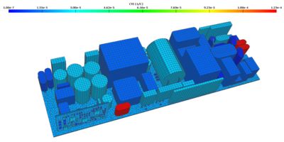
An example of a finite element analysis simulation in Ansys Sherlock
Generating model geometry is one of the most difficult aspects of FEA. A common mistake among beginner FEA users is assuming that a computer-aided design (CAD) model created as part of the product design process can be plugged directly into an FEA study. Designers’ CAD models typically include tremendous detail, which would take hours or days of processing to incorporate into a simulation analysis.
Watch the on-demand webinar ‘ECAD to FEA in 5 minutes’ to learn more.
However, much of this detail is often unnecessary in FEA. Worse, the inclusion of unnecessary details in an FEA model can result in poor quality meshes, inefficient simulations run times and inaccurate results.
For an analyst, understanding when and how to simplify a model that was passed to them by a designer is a key skill for an effective FEA simulation.
Finite Element Analysis Optimization: Removing Unnecessary Object Features
Perhaps the most common details that can be immediately removed from most CAD models are the fillets and rounds. Truly square edges rarely exist in the real world. Edges are typically rounded and CAD models will often include this rounding on many, if not all, of the geometric bodies. However, square edges are much easier for meshing in the FEA world, and most small fillets/rounds will not affect global displacement calculations. CAD tools will typically have a feature to aid in the removal of fillets/rounds, like the fill command in Ansys SpaceClaim. Appropriately using these features can rapidly decrease model complexity with little user effort.
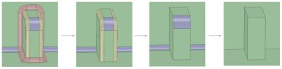
Incremental round removal in Ansys SpaceClaim
Incorporating Effective Geometries and Constraints
Another common simplification is removing insignificant bodies or replacing them with effective geometries or constraints. For example, most mechanical assemblies include fasteners, like bolts and rivets. Sometimes, it may be necessary to include the geometry of a bolt in the model; however, in many cases, bolt geometries can be replaced with greatly simplified 3D geometries, 1D beam elements or even removed entirely and approximated with rigid contact constraints or fixed boundary conditions.
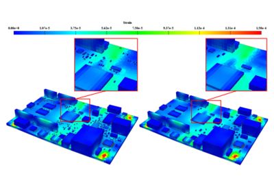
Mechanical shock results show negligible global and local results when very small
chip components are included (left) vs. when they are excluded (right).
For example, if mechanical shock is being simulated on a 12x12-inchprinted circuit board assembly(PCBA), very small components like 0201 resistors will have no effect on the global stiffness of the model and can be removed entirely. Larger components like a 16 PIN SOIC may need to be modeled, but the solder can be replaced and approximated with a rigid contact between the leads and the board. Ansys Sherlock is a tool that can aid in generating an FEA-ready model from information available at the design stage of a PCBA by taking in the ECAD information meant for PCBA manufacturing and automating the creation of a simplified, meshed, FEA-ready PCBA model.
How to Improve an FEA Model: Proper Mesh Generation
Beyond defeaturing a model, there are a number of decisions needed to be made for proper mesh generation. There are typically three areas that Ansys-DfR considers when creating accurate meshes:
- Choosing shell vs. solid elements
- Choosing hex (brick) vs. tet (pyramids) elements
- Choosing the proper mesh size and mesh order
Shell vs. Solid Element
More often than not, CAD geometry will be composed entirely of three-dimensional bodies. However, in an FEA model, it may be advantageous to mesh some of those bodies with shell elements rather than solid 3D elements.
Shell elements are 2D approximations of the 3D geometry that store the thickness of a body as a physical property. They can be used for thin-walled geometries with a length much greater than the thickness of the body, and when the shear deformation is insignificant (e.g., a sheet metal chassis or the walls on a soda can). There are also special shell and beam reinforcement elements that can be used to model the thin copper layers inside a printed circuit board (PCB).
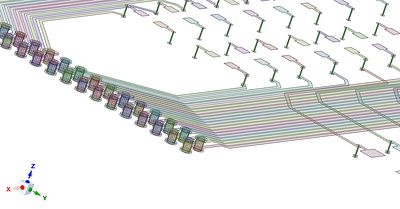
Copper PCB features modeled as shell and beam reinforcements
New features in Ansys Sherlock allow for the rapid generation of these reinforcement geometries. These reinforcements enable the user to capture the effect the traces have on the board deformations efficiently.
Furthermore, properly incorporating shell elements into FEA models can greatly improve both simulation run time and the accuracy of results. When used appropriately, shell elements can typically generate a higher quality mesh on thin-walled structures (like sheet metal) with a much lower element count, resulting in more accurate results at a significantly reduced computational cost. CAD tools like the “Create Midsurface” feature in Ansys SpaceClaim can aid in preparing geometries for shell meshing.
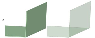
Solid body (left) replaced with surface body (right) using the Ansys SpaceClaim Midsurface Tool.
It may seem intuitive to assume that 3D meshing yields more detail, which provides more accurate results. But this is not always the case. Particularly in cases of large bending, solid elements often create artificially stiff structures when they are used to mesh thin-walled geometries, resulting in inaccurate simulations. In addition, it can be very difficult to refine the mesh and generate enough elements through the thickness of a thin-walled structure to achieve accurate displacement and stress results.
Furthermore, if the geometry is complex enough, thin-walled structures may result in a poor-quality mesh when solid elements are used, creating sliver-like elements with poor aspect ratios, negatively affecting results.
Hex vs. Tet Elements
When determining whether to use hexahedral (hex) elements or tetrahedral (tet) elements in an FEA model configuration, it’s important to keep in mind the overall shape and complexity of the object itself. The general rule of thumb is to mesh with hexahedral elements if possible. Hex or “brick” elements generally result in more accurate results at lower element counts than tetrahedral elements. However, if the object contains acute angles or other complex geometries, it may be necessary to mesh with tetrahedral elements.
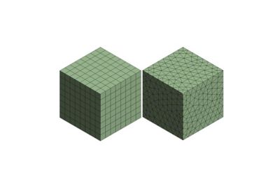
An identical body meshed with hex elements (left) and tet elements (right).
It is preferable to simplify the model enough to mesh it entirely with bricks, but this is not always feasible. For complex geometries that require tet meshes, take care to ensure the mesh does not result in inaccurate results. This usually means higher element counts, high order elements and longer run times.
For these reasons, any model simplifications like fillet removal or body splitting that allow for hex meshing without significantly changing the geometry are highly recommended.
Mesh Size and Order
Properly understanding mesh order and size are key to finding the balance between accurate results and reasonable run times in a finite element analysis.
Mesh size simply refers to the characteristic edge length of an element. A smaller mesh size will result in more elements in the model, resulting in longer run times and more accurate results. Order describes the shape function used to calculate element displacements.
First-order elements have nodes only at the corners of the elements and calculate displacement linearly between nodes. Second-order elements include midside nodes between the corners and calculate displacement quadratically. The additional detail in second-order elements typically results in increased accuracy, but at a significantly increased computational cost.
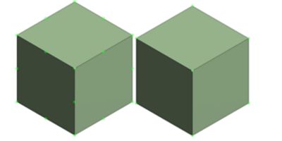
A quadratic element (left) and a linear element (right). Nodes are highlighted in green.
Note the midside nodes in between the corners on the second-order element.
The key to generating effective FEA meshes is to strike an appropriate balance between order and size for the particular problem that is being analyzed. When possible, use second-order elements and iteratively refine the mesh until the results converge. However, for much larger problems that solve on the order of days even with high-performance computing, this may not be feasible. In these cases, an analyst will need to use experience to make appropriate decisions regarding mesh size and order.
How to Improve an FEA Model: Proper Load Applications
Determining proper load applications is an important FEA step. Load applications are the model inputs that the object is being tested for, such as a specific event like a thermal cycle, shock from a drop, vibration or static flexure. Understanding the nuances of how to apply the loads are essential to simulate an event that the object will face in a real-world environment.
One common example is determining whether loads applied should be applied as static or transient. For example, if an engineer is simulating the flexure of a structure during assembly, it may be acceptable to model the load as a static displacement because strain rates are likely to be much slower and results time-independent. However, if an engineer is modeling a similar deflection caused by dropping the same assembly, they would likely need to use a transient model to capture the associated inertial effects, because the application time of the load is much faster and time-dependent effects must be captured.
In the electronics simulation world, we often deal with a similar case when simulating thermal cycling. For example, when investigating thermal expansion at the board level (rather than the component level), linear material property approximations can often be used and static, time-independent ramps to temperatures may be reasonable. This is acceptable when board-level displacement and elastic stresses/strains are the focus of an analysis rather than creep strains/energies. However, when investigating component-level solder fatigue, time-dependent solder creep properties must be included. In this case it is important to accurately apply the ramp and dwell times of the thermal cycle, rather than simply ramping the temperature up linearly. Creep models include time-dependent properties, so the simulated cycles must be modeled in their entirety to most accurately calculate creep strain/energy results that are used to make solder fatigue predictions.
The same real-world event is not always equal in the FEA world depending on the desired outcome of the analysis. It’s important to always keep in mind the real-world stressors the object will likely face and how those stressors could affect the component of interest. Inputting these nuances properly will result in an analysis that is accurate, valid and actionable.
With the right pre-processing, you can significantly increase the speed of FEA without affecting its accuracy.
Watch the on-demand webinar ECAD to FEA in 5 Minutes to learn more.
