-
-
Software gratuito per studenti
Ansys potenzia la nuova generazione di ingegneri
Gli studenti hanno accesso gratuito a software di simulazione di livello mondiale.
-
Connettiti subito con Ansys!
Progetta il tuo futuro
Connettiti a Ansys per scoprire come la simulazione può potenziare la tua prossima innovazione.
Customer Center
Supporto
Partner Community
Contatta l'ufficio vendite
Per Stati Uniti e Canada
Accedi
Prove Gratuite
Prodotti & Servizi
Scopri
Chi Siamo
Back
Prodotti & Servizi
Back
Scopri
Ansys potenzia la nuova generazione di ingegneri
Gli studenti hanno accesso gratuito a software di simulazione di livello mondiale.
Back
Chi Siamo
Progetta il tuo futuro
Connettiti a Ansys per scoprire come la simulazione può potenziare la tua prossima innovazione.
Customer Center
Supporto
Partner Community
Contatta l'ufficio vendite
Per Stati Uniti e Canada
Accedi
Prove Gratuite
ANSYS BLOG
April 28, 2021
The Fundamentals of FEA Meshing for Structural Analysis
Simulation is a critical tool for many industries and the global simulation software market is expected to grow at a compound annual growth rate (CAGR) of 8-9% in the next few years. This is a substantial increase — primarily due to the many benefits simulation software provides business, including reductions in product development costs, physical tests and faulty prototypes.
In computer-aided engineering (CAE) applications like simulation, there are types of software to analyze your product such as finite element analysis (FEA), computational fluid dynamics (CFD) and many others. To conduct a CAE simulation, there are three important steps to an analysis: pre-processing, solving and post-processing. Let’s discuss the FEA pre-processing step, specifically the importance of a good quality mesh.
Learn more about how to mesh and simulate welds and how to maintain a high-quality mesh in our other FEA meshing blogs.

An example mesh on a gearbox casing part.
What is Meshing in FEA?
Finite element analysis (FEA) is a mathematical representation of a physical system comprising a part/assembly, material properties and boundary conditions. In several situations, product behavior in the real-world cannot be approximated by simple hand calculations. A general technique like FEA is a convenient method to represent complex behaviors by accurately capturing physical phenomena using partial differential equations. FEA has matured and has been democratized so that it can be used both by design engineers and specialists.
Meshing is one of the most important steps in performing an accurate simulation using FEA. A mesh is made up of elements which contain nodes (coordinate locations in space that can vary by element type) that represent the shape of the geometry. An FEA solver cannot easily work with irregular shapes, but it is much happier with common shapes like cubes. Meshing is the process of turning irregular shapes into more recognizable volumes called “elements.”
Before you start meshing, you must first upload a geometry or CAD model into, for example, Ansys Mechanical to begin the simulation process.
How to Prep your CAD/Geometry for Meshing
When using FEA simulation software, such as Mechanical, it’s important to determine what features from your CAD model need to be meshed and what features don’t. Many times, CAD geometry is very complex and detailed for manufacturing purposes. But for a simulation, you may not need every detail so parts of your geometry can be defeatured, which means removing those details to save time.
For example, your product may have a name plate attached. You may not need to learn the physical effects of this name plate, so the plate can be defeatured to avoid creating a mesh, which saves meshing and solve time.
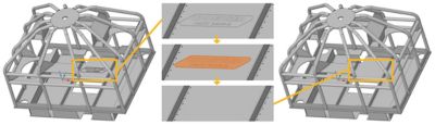
Using Ansys SpaceClaim, the name plate on the geometry was easily defeatured to avoid doing a potential unnecessary analysis on the plate.
Another important aspect of prepping your CAD model for simulation is describing the relationship between two or more parts in your geometry. For example, if your geometry shares nodes between common faces (or edges), it’s important to decide if it will be a conformal or nonconformal mesh. A conformal mesh is used for parts joined by glue or welds. A nonconformal mesh is used for parts joined by contacts or joints. In Ansys Mechanical, you can mix these approaches to fit your needs.
Read the 3 Steps to Improve Your FEA Model blog to learn more.
Types of Meshing Methods: Tetrahedral vs. Hexahedral
There are two main types of meshing methods. For these purposes, we are referring to 3D models:
- Tetrahedal element meshing or “tet”
- Hexahedral element meshing or “hex”
Hex or “brick” elements generally result in more accurate results at lower element counts than tet elements. If it is a complex geometry, tet elements may be the best choice. These default or automatic meshing methods may be enough to get you where you need to go, however, there are additional methods that can give you more mesh control.
Hybrid Meshing
In Mechanical, you can use a Multizone method, which is a hybrid of hex and tet elements that allows you to mesh different parts of the geometry with different methods. This allows you to perform less geometry preparation and have more local control meshes.
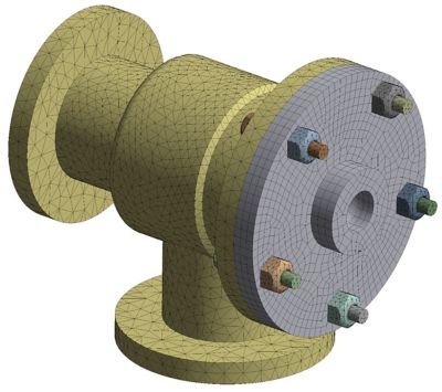
A pipe connection geometry using Ansys Mechanical’s hybrid meshing capabilities
Sweep Meshing
With sweep meshing, the mesh actually “sweeps” the mesh through the volume and faces to help create an efficient mesh with regular sizing.
Deciding which mesh method to use usually depends on what type of analysis (explicit or implicit) or physics you are solving for and the level of accuracy you want to achieve. A few other options are cartesian meshing and layered tets that are used for specific analyses like additive manufacturing.
Meshing Controls
Meshing controls enable a more precise mesh. Ansys Mechanical enables you to control local meshes, instead of a global mesh that meshes the entire CAD with the same method. Some examples of local meshing controls include local sizing, refinement and sphere of influence defeaturing of the geometry.
Let’s take a motorcycle frame for example. You may want to apply a general mesh approach across the entire geometry but use a different strategy where the weld and bolted connections are. Using local meshing controls allows you to create a more refined mesh at these locations and not mesh the entire part with smaller elements, which would take longer to solve.
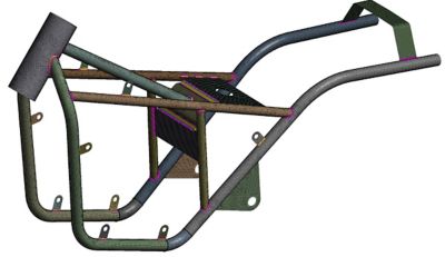
A motorcycle frame geometry meshed showing welded joints.
Why is A Good Quality Mesh Important?
Simply put, a good quality mesh equals more precise results. A poor mesh can result in convergence difficulties, which can lead to incorrect results and false conclusions. The quality of your mesh depends on a few scenarios:
- What type of analysis you are conducting.
- How much time you want to invest in the mesh.
- How much time you want to invest in solving.
In some instances, you may be looking for a quick solution — something that will help clarify a design decision. In this instance, you may not want to spend a lot of time setting up your mesh. Other times, you may want a very precise solution or result, which would require some time and effort into setting up your mesh with different methods and controls.
A good mesh has a quality criterion that fits your needs (analysis type, level of accuracy, time) such as element quality and aspect ratio. Ultimately, we recommend understanding your geometry and using controls to get the best mesh possible — which, after all, leads to a better product design.
Learn more in our Intro to Meshing Course on the Ansys Learning Hub, or watch the webinar Ansys Multiphysics Simulation for Crack Propagation Analysis.