-
-
Access Free Student Software
Ansys empowers the next generation of engineers
Students get free access to world-class simulation software.
-
Connect with Ansys Now!
Design your future
Connect with Ansys to explore how simulation can power your next breakthrough.
Countries & Regions
Free Trials
Products & Services
Learn
About
Back
Products & Services
Back
Learn
Ansys empowers the next generation of engineers
Students get free access to world-class simulation software.
Back
About
Design your future
Connect with Ansys to explore how simulation can power your next breakthrough.
Free Trials
ANSYS ADVANTAGE
JANUARY 2022
Magma Global is an innovative, fast-growing subsea technology company at the leading edge of carbon fiber composite development. Magma uses the most advanced materials and manufacturing science to deliver innovative solutions to the subsea oil and gas industry, with products deployed in some of the harshest conditions on the planet.
One of those products is m-pipe, which has been used for flowlines and jumpers, intervention systems and flying leads around the world, delivering hydrocarbon, water and gas. The flexibility of m-pipe defies its strength. It has a minimum bend radius that allows it to be delivered on standard reels, which together with its light weight makes it possible to deploy from smaller vessels.
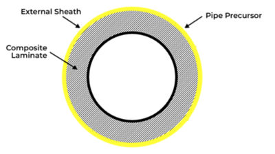
M-pipe cross-section
The advanced engineering team at Magma are continuously refining the design of m-pipe laminate layers to optimize strength and minimize weight, while ensuring the polyether ether ketone (PEEK) and carbon fiber pipes are cost-effective to manufacture.
Minimizing the amount of thermoplastic composite within each new m-pipe reduces the consumption of fossil fuels used in the manufacturing process. Compared to traditional steel pipe installation, the lightweight nature of m-pipe also minimizes installation costs and allows smaller service vessels to be used. In addition, m-pipe requires fewer offshore trips, which further reduces the carbon footprint.
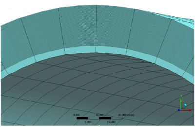
Example of pipe body composite laminate
Ansys Workbench finite element analysis (FEA) software has enabled the reduction of thermoplastics within m-pipe via realistic simulations, which replicate actual test behavior in the structural response of an accurate numerical model. This is then used to reproduce in-service load combinations.
Prior to investing in Ansys simulation software, Magma’s design process was like most in the industry. Engineers would develop a few designs for a particular customer’s application and subject them to a series of physical tests, which can be costly and time-consuming.
The objective of the simulation process is to reduce the quantity of raw material used while still delivering m-pipe within very short lead times and satisfying DNV qualification requirements. DNV is an international accredited registrar and classification society.
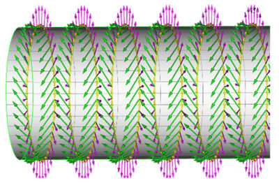
Example of pipe body composite ply orientation
Simulating Service Life Conditions for Thermoplastic Composite Pipe (TCP)
Using Ansys simulation solutions, Magma engineers are simulating structural tests numerically through virtual models. The results are then used to reproduce actual service life load combinations. Magma Global can quickly produce a qualified product that exceeds customer requirements through the entire design cycle including decommissioning.
Numerical simulation with Ansys Workbench finite element analysis (FEA) enabled our computer-aided engineering (CAE) team to quickly consider different options through efficient scripts within Workbench. Numerous FEA iterations can be run to validate the structural integrity of the m-pipe. The number of physical tests has been dramatically reduced; now their sole purpose is to confirm the simulation results. Each physical test is also strain-gauged to correlate the results against the numerical model.
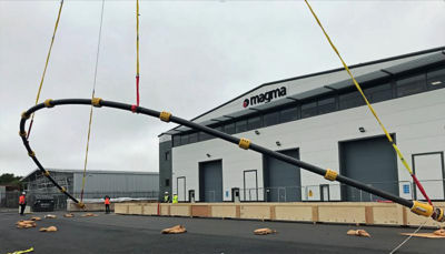
Example m-pipe lifting operation
Estimating m-pipe service life using simulation gives our customers more confidence in our products. We not only share structural analysis results, including stress and strain plots, but we also interface with DNV to gain classification approval. Simulation helps us to produce some of the most robust thermoplastic composite pipe in the oil and gas sector. Using the least possible material, these pipes can still cope with the extreme operating conditions required of oil and gas components. This helps to keep product costs low so we can compete successfully with other suppliers.
Magma’s CAE Process
Although the concept of a composite pipe appears relatively simple, in practice the numerical models are extremely complex. The laminate can comprise over 50 layers, with each layer oriented to optimize structural performance while remaining within manufacturing parameters. A metallic end fitting is secured at either end to provide a robust connection to third-party equipment. The analysis sequence simulates the service life of the product, which covers storage, transportation, testing, installation and operation.
Example of end fitting stress plot
The first step is usually an investigation using Orcaflex (dynamic analysis software tuned for sub-sea systems) to determine the system’s global response. The local forces and moments are extracted and applied to the pipe body and end fitting FEA models. Orcaflex is also used to simulate transpooling operations of the pipe around the Magma site as it comes off the manufacturing reels on to storage reels or for lifting operations, as shown below.
Pipe Body Finite Element Analysis
We have developed our own pipe body “Magma Ansys Pre and Post Processor” (MAPPS) interface, which is driven via a Microsoft Excel interface to create a parametric Ansys Parametric Design Language (APDL) script. MAPPS provides an easy-to-use design tool for all Magma engineers, even those without in-depth knowledge of Ansys software.
The following input parameters are required:
- Pipe geometry
- Element density
- Ply configuration: thickness and orientation
- Laminate build-up
- External loading (pressure, axial force, bending moment, etc.)
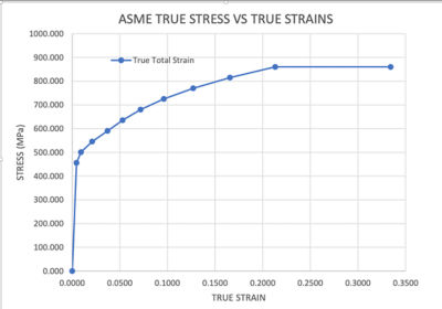
Example stress-strain curve
From the above data, a 3D FEA model is created using 20-node layered elements with quadratic behavior, which are required for modeling thick composites. MAPPS also allows the input of individual ply properties and the retrieval of stress and strain results.
Ply material properties are a key aspect of any composite model. We have completed extensive physical testing to derive this information, which forms the basis of our simulation models. Each simulation is run on a dedicated analytical server and takes seconds to complete, which allows laminate construction to be quickly optimized using our MAPPS results graphical interface.
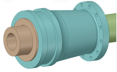
Example of end fitting CAD geometry
The pipe body is designed in accordance with DNV-ST-F119 and DNV-ST-C501 using the limit state design method. This approach assesses the following three failure mechanisms:
- Fiber dominated ply failure, based on total strain
- Pipe body failure in response to axial loads
- Pipe body collapse from elastic buckling
As m-pipe composite laminate is composed of numerous lamina at differing angles and potential different material characteristics, assessing them individually ensures we don’t exceed the various failure criteria. Ansys Workbench has efficient post-processing tools to help with this, and they incorporate the following failure checks: max. strain, max. stress, Tsai-Wu, Tsai-Hill, Hashin, LaRC, and Cuntze. We use the maximum strain failure criteria to carefully assess the fibers and matrix within each ply, both along the length of the pipe and through the laminate thickness.
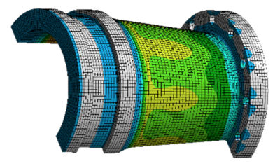
In addition, component results are also oriented into the pipe system axis to determine axial, hoop and radial values. Example displacement and pipe axial strain results are shown below.
End-Fitting Finite Element Analysis
The end-fitting assemblies are fabricated from super duplex stainless steel, which is used extensively for subsea equipment. It comprises an arrangement of concentric components that generate a radially compressive pressure that sandwiches the pipe body without the need for bolts or pinned connections, which would compromise the laminate integrity.
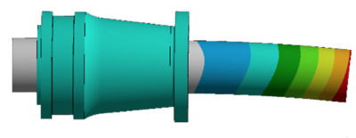
Example of end fitting deformed shape
The structural analysis is performed using an FEA assembly model created based on computer-aided design (CAD) geometry provided by the design team. Minor features, such as threads, non-critical holes and small blend radii are then easily removed using Ansys SpaceClaim.
To allow the application of external loads, the end fitting FEA model includes a section of the pipe body . This typically extends five times the pipe outside diameter beyond the end fitting interface to eliminate any end effects. Sensitivity studies are undertaken to ensure the element density is adequate in critical areas, e.g., stress concentrations. The element quality, which is the ratio of the volume to the edge length, is checked to ensure a minimum value of 0.2 is maintained.
The end-fitting is designed in accordance with Section F100 of DNV-OS-F101, which requires mechanical connectors to be designed against ASME VIII Division 2. To verify the design of the end fitting, the following design checks are performed:
- Protection against plastic collapse
- Protection against local failure
- Protection against hydrogen-induced stress cracking (HISC) in accordance with DNV-RP-F112
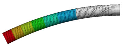
Example of pipe body deformed shape
To accurately simulate the load path through the end-fitting assembly, contact between individual components, including the effect of friction, is determined. Stress-strain curves are defined for the super duplex material, including the effect of temperature. This, in combination with the contact, means the analyses include the effects of both nonlinear materials and geometry.
To represent each service condition, a sequential loading combination is applied to the FE model as a series of nonlinear steps. This can mean up to 10 load steps are applied, including thermal expansion, pressure, axial tension and bending moment.
Because operators are continuously developing the level of accuracy in the end fitting FEA model, the complexity increases accordingly, escalating the solution time. To minimize this, operators optimize both the Ansys solver parameters and CPU cores.
As part of the detailed ASME integrity checks, operators extract component stresses and strains from the FEA model across all load combinations. This includes Von-Mises stress, equivalent plastic strain and the ratio of equivalent plastic strain to the triaxial strain. To assess protection against hydrogen induced stress cracking (HISC), operators carry out two further strain checks that include the use of the linearization technique within Workbench to extract an average strain value through the component wall thickness.
Presenting virtual results helps operators understand the behavior of m-pipe. Our analysis provides clear, concise information that can easily be interpreted by all parties. The outcome is less risk, along with greater customer involvement and confidence up front.
As part of our ISO 9001 quality assurance system, a thorough independent check is undertaken on each new FEA model to ensure the assumptions are correct and the subsequent results are acceptable. A technical report is also submitted to the client or DNV for review.
Future Digital Engineering Developments
Our investment in digital engineering has enabled our operators to design and prove the most cost-effective, high-performance pipe at a minimal engineering cost. We plan to extend the Magma standard Ansys material library, further refine integrity checks, automate the post-processing of results, and improve contact behavior to reduce solution times further. Our engineering tools dramatically reduce testing time and expedite projects efficiently and accurately.
Let’s Get Started
If you're facing engineering challenges, our team is here to assist. With a wealth of experience and a commitment to innovation, we invite you to reach out to us. Let's collaborate to turn your engineering obstacles into opportunities for growth and success. Contact us today to start the conversation.