Synopsys and Ansys power the future of innovation—connecting silicon to systems.
主題詳細資料
什麼是電腦輔助 工程 (CAE)?
電腦輔助工程 (CAE) 是一項工程領域的分支,其使用軟體工具進行數位模擬,並最佳化產品設計。CAE 應用於各個產業中,可協助失效分析、改善效能、降低開發成本、縮短設計週期,並讓工程師深入瞭解產品的效能。
CAE 工具起初發展於航太產業,如今已演進為工程流程中不可或缺的一環,通常在實體原型問世前,就已驅動著產品開發的決策。能夠以虛擬方式測試真實世界情境、回答關鍵設計問題,並在設計流程初期驗證產品功能及效能,讓投資 CAE 工具與技術在工程領域中成為報酬率最高的一種選擇。
CAE 工具會建立一個數學模型,用以描述在外加負載作用時,特定幾何、材料、連接與約束的表現。任何 CAE 模擬的目標,都是定義已知系統的數量並計算未知量。CAE 在一些情況下可能可以取代實體測試;但若仍需要進行真實世界測試,也可用於減少迭代次數。
CAE 常用術語
在深入介紹工程師進行 CAE 時使用的三步驟流程之前,我們先來認識幾個常見術語。
- 負載:作用於數位模型上的外力或能量變化。
- 約束:模型中以自由度表示,並由使用者固定的特徵值。
- 邊界條件:施加於模型的負載與約束。
- 連接:定義模型中各物件之間的物理量傳遞方式。這些通常是負載或約束,例如壓力或位移。
- 材料屬性:定義特定材料在施加邊界條件時會如何表現。剛度、傳導性和密度等屬性為材料屬性。
- 模型:已知屬性及其在外負載作用下反應方式的數學表徵。
- 網格與網格劃分:許多 CAE 工具會將模型網域劃分為離散的幾何區域或體積,稱為網格單元或元素。這些元素及其連接關係的數學定義就是網格,網格劃分則是離散化的過程。
- 求解器:係指根據一組已知量求解未知量所用的演算法。
- 結果:已求解未知量的數值表示。
CAE 模擬流程
無論 CAE 應用於何處,從業人員通常會遵循三個步驟:前處理、求解和後處理。各步驟的複雜程度會依模擬所納入的物理現象、所需準確度、產品複雜度,以及數位模型中所呈現的操作環境複雜度而異。另外,此流程始終是以工程團隊希望從模擬中取得哪些資訊所驅動。
以下是標準的三個步驟。
前處理:描述問題
前處理是 CAE 工作流程中的第一步,也是最重要的一步。在此階段,工程師會記錄已知的值,使用 CAE 軟體將幾何離散化,並將所有必要資料擷取到資料庫中。多數模型建構都會先取得系統中的幾何或元件,然後將幾何離散化,也就是進行網格劃分。接著,使用者必須施加約束,以定義特定的物理數值,並定義作用於幾何上的負載。使用者也必須指定所用各種材料的屬性、元件之間的連接,以及邊界條件如何隨著時間變化。工程師執行 CAE 模擬的最後一項任務,為指定求解器執行工作所需的輸入與變數,藉此名血指定該如何求解特定的數學問題。
前處理相當重要,因為求解器會計算問題的輸出;若輸入不正確,輸出就無法反映真實世界的情況。這就是典型的垃圾進、垃圾出 (GIGO) 情況。此外,瞭解自動化及與電腦輔助設計 (CAD) 幾何工具緊密連結能夠加速前處理且提高其準確度也至關重要。
求解:建立數學模型並求解
求解是指對軟體在前處理階段所建立的數學表徵進行實際處理。首先,求解器會將數學定義轉換成一組方程式,通常是偏微分方程,其中包含已知值及未知值。接著,使用數值方法進行大量方程式的求解,以取得未知值。雖然,工程師會使用軟體針對未知值求解,但有些演算法會消耗大量的記憶體、磁碟空間和 CPU 運算週期。在為許多 CAE 模型求解時,使用高效率求解器方法與高效能運算資源,可說是相當重要。
後處理查看求解結果
求解步驟產生的結果,會以數字形式儲存在資料庫。工程師為了運用這些數值,需要使用 CAE 軟體,將其轉換為有用的表示方式。後處理階段產生的常見結果表示方式,包括:
- 圖表
- 以顏色表示結果值的幾何
- 在指定數值下,將場域結果以表面形式呈現
- 以流線呈現流體運動、以箭頭呈現場值,或以射線呈現光線路徑
- 變形幾何
- 表格
- 包含結果值及這些數值之座標位置的電腦檔案
以顏色表示數值的幾何圖,是後處理中最常產生的輸出類型。在大多數情況下,工程師會使用後處理提供資訊,藉此驗證與確認設計,或協助作出設計或製程中的決策。
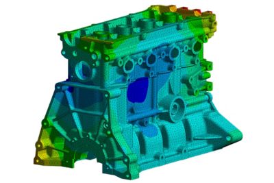
一個典型結果圖範例,其中撓度以顏色形式呈現至網格表面上。紅色表示最大撓度,深藍色表示最小撓度。
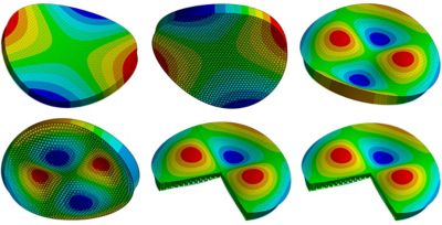
望遠鏡中鏡片的振動分析結果,顯示其自然頻率,並以誇大撓度與顏色表示撓度值
 在 Ansys Fluent 流體模擬軟體中,圓柱繞流的經典範例,以色彩編碼流線顯示
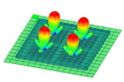
Ansys HFSS 高頻電磁模擬軟體中,相位陣列天線的電磁場值
重複步驟以進行迭代與設計最佳化
CAE 的一個重要部分就是修改模型並重新進行求解,以評估這些變更如何影響結果。這可以由工程師遵循手動工作流程完成,也可以透過自動化迴圈完成;這類迴圈稱為最佳化,會使用演算法以參數化方式改變輸入,並收斂至期望的輸出值。大多數現代 CAE 軟體都包含指令碼功能,讓工程師能夠自動化並控制這些迭代。慢慢地,這可以透過 Python API 完成,例如 PyAnsys,這是以 Python 形式存取 Ansys CAE 工具系列中所具 Ansys 軟體的工具。
最常見的電腦輔助工程類型
從技術上來說,CAE 是使用電腦參與計算產品行為的任何一種模擬類型。工程師可以依據欲求解的物理類型,或依據所使用的求解器類型進行模擬的分類。
依物理類型分類的 CAE 類型
- 結構與機械:
- 結構分析:材料在靜態負載下的撓度與變形。
- 動態分析:材料在隨時間變化的負載下產生的撓度,以及自然頻率響應。其中還包括聲學模擬。
- 顯式動力學:短時間內的撓度與變形。
- 多體動力學 (MBD):系統中各物體之間的相對位移;若不考慮動量,則是建模運動學。
- 熱與流體
- 熱力學:系統中的熱生成與能量傳遞。
- 燃燒與分子動力學:源自化學反應的熱生成。
- 熱傳遞或散熱分析:熱由於對流、傳導與輻射而在系統中移動。
- 計算流體力學 (CFD):系統中的流體流動,求解納維爾-斯托克斯方程式。
- 電子與電磁學:
- 電路模擬:電氣系統中的電流流動與電壓值。
- 邏輯與 RTL 模擬:電路中的數位訊號。
- 低頻電磁學:波長遠大於物體的電磁場。
- 高頻電磁學:波長小於物體的電磁場。
- 訊號完整性模擬:不同電路之間互相作用的訊號。
- 其他:
- 系統模擬 (1-D):系統的「區塊」表徵,其中每個區塊代表系統中的一個元件。
- 流程模擬:任何流程類型的 1D 模擬,範圍從化學製程到供應鏈。
- 技術 CAD:積體電路 (IC) 中的電晶體物理運作。
- 光學模擬:光的移動,包括折射、反射、輻射和吸收。
- 多物理:在單一模擬中結合任兩種物理。最常見的是流固耦合 (FSI)和電熱耦合。
依求解器分類的 CAE 類型
不同物理類型可透過多種求解器類型求解。例如,熱傳遞模擬可以使用有限元素、有限差分或有限體積求解器以計算熱流。
以下是工程師在說明使用的 CAE 方法時,最常提到的求解器類型:
- 有限元素分析 (FEA):把幾何模型切分成許多小元素,再用線性代數進行計算。FEA 是 CAE 中最常見的求解器方法,主要用於結構、電磁與散熱分析。
- 有限差分分析 (FDM):計算一個模型中離散點的未知值。常用於系統、電路與製程建模;採用簡單的方式表示,有時可即時進行求解。
- 有限體積分析 (FVM):在小體積範圍內計算未知值,同時保持能量或質量守恆。這是 CFD 最常見的求解器類型。
- 邊界元素分析 (BEM):使用系統中物體表面的離散化表示以求解場。
- 離散元素法 (DEM):計算個別粒子的位置與動量。用於建模岩石、顆粒或粉末等散裝材料的粒子行為。
- 平滑粒子流體動力學 (SPH):使用液滴而非體積以求解流體中的未知量。適用於晃動與波浪。
- 光線追蹤:計算光與聲音的速度、能量、反射、折射和吸收。
其他電腦輔助技術 (CAx)
運用電腦支援整個產品生命週期中的其他步驟,便能進一步有效運用 CAE 解決方案,這些步驟包括產品開發流程、製造與維護。各領域不僅可以透過數位工程方法獲得龐大同等效益,資料亦能更容易流入與流出 CAE 工具。
最常見的電腦輔助領域形式有:
- 電腦輔助設計 (CAD):用於產品開發的軟體,開始於從 2D 實體圖面轉向 CAD 圖面,之後再發展為實體模型。數十年來,使用 CAD 已成為業界標準。幾乎所有的 CAE 工具都支援與 CAD 工具緊密結合,以利交換使用幾何與尺寸參數。
- 電子電腦輔助設計 (ECAD):ECAD 與土木及機械工程所見的 CAD 類似,這是一套協助開發產品的電腦軟體工具,著重在於電氣系統組態。ECAD 用於產品定義,其範圍涵蓋積體電路中的電晶體,再到多層印刷電路板 (PCB) 的佈局。電子設計自動化 (EDA) 一詞,是指協助工程師設計、模擬、驗證和製造 PCB 與積體電路的工具。
- 電腦輔助製造 (CAM):CAD 也會結合相關工具,以協助使用 CAM 軟體進行製造規劃與執行。CAM 工具可用於各種作業,涵蓋編寫電腦數值控制 (CNC) 加工系統的程式,到機器人與自動化組裝線等。
- 電腦輔助製程規劃 (CAPP):製造與製程工程師也會使用 CAPP 工具,以規劃和最佳化製程,有時則整合 CAE 工具,針對各種方案進行虛擬原型設計。
CAE 的進展
在 CAE 領域,唯一不變的是持續改進的能力與持續提升的速度,並善用進化的電腦硬體、數值方法和使用者介面設計所帶來的優勢。這項趨勢仍將持續下去,同樣聚焦於提升準確度、易用性和求解器效能。
以下是預期在未來幾年會帶來改善的一些技術進展。
生成式人工智慧 (AI)
CAE 軟體在數十年來持續使用 AI,尤其是機器學習 (ML) 和專家系統。目前的研究重點圍繞在神經網路,以及將大型語言模型納入使用者體驗與求解器。使用者已可在使用者介面中運用這項技術,例如在許多 Ansys 工具的前處理與後處理中使用 Ansys Engineering Copilot;在求解器方面,則是用於模擬的 Ansys SimAI AI 平台、用於幾何的 Ansys GeomAI AI 平台,以及 Ansys TwinAI AI 驅動數位孿生軟體。
圖形處理器 (GPU)
CAE 求解器同樣受惠於圖形處理和生成式 AI 模型訓練所採用的向量運算大規模平行化技術。程式設計人員可精簡線性代數演算法,支援更龐大的模型,並加快求解速度。
積體電路微縮化且電源管理獲得改善
CPU、GPU 和記憶體 IC 的改進也是如此。更小的特徵尺寸可容納更多電晶體,同時提高時脈速度,CAE 工具也從中受益。值得留意的是,CAE 工具對於這些改良晶片的設計極具關鍵。
全面投入電腦輔助工程的產業
航太產業是 CAE 工具最早開始創造價值的領域,但其使用已擴展至各個產業。下面是一些已將 CAE 工作流程導入設計工作流程的產業:
- 航太與國防 (A&D):自 1970 年代以來,CAE 一直是航太與國防產品開發和生命週期管理不可或缺的一部分,至今仍是工作流程中的關鍵要素。廣獲使用的促因在於該產業的高成本、低產量、難以測試的環境及重大安全考量等特質。
- 汽車:汽車業採用 CAE 的程度,隨著時間推移已逐漸與航太與國防產業並駕齊驅。使用上不僅包括同樣重要的安全考量,亦受到汽車結構日益複雜、市場競爭激烈及成本壓力所推動。
- 營建環境:興建土木工程大型結構物的工程師,也能在整個流程中應用 CAE 而獲益良多。CAE 一直是結構工程的基礎,隨著建築物、公路、污水系統等系統模擬的發展,使用量也持續成長。此產業是數位孿生的早期採用者。
- 電子:現代積體電路若沒有使用 CAE 工具推動並驗證設計,就無法完成設計。複雜電子系統的冷卻、封裝和製造,亦高度仰賴工程師使用 CAE 軟體進行設計與最佳化。
- 發電:另一群早期採用 CAE 的使用者,則是設計、建造與維護發電設備和電廠的工程師。從蒸汽渦輪機到模組化核反應爐,幾乎每個元件與系統都以虛擬方式建模和測試。
- 採礦、石油與天然氣探勘及開採:由於高成本且高報酬,從事尋找與開採自然資源的工程師,會使用模擬工具尋找礦藏,然後設計用於開採資源的機器與系統。
世界級 CAE 軟體範例
從工程師擁有為數龐大的選擇,便能看出 CAE 軟體工具的價值。團隊在決定使用哪些工具時,應考慮以下幾點:
- 它是否能提供開發產品所需的資訊?
- 它是否能與自身的 CAD 無縫互動,並具備雙向參數化功能?
- 它是否容易學習和使用?
- 它是否提供實用的線上文件與支援,並在需要之際,提供具備專業知識的人員支援?
- 是否有大量使用者可供聘僱或委外合作?
- 求解器是否現代化且高效率,它有沒有善用最新的硬體技術?
- 開發團隊是否持續開發新的以及更好的功能?
- 它是否支援多物理分析?
- 它是否具備強大的後處理功能,能將求解結果迅速轉換為可用形式?
- 我們的團隊是否能輕鬆自訂前處理器或自動化任務?
- 最佳化與參數化研究是否一開始就內建於其中?
Ansys (現已與 Synopsys 合而為一) 的工具套件能針對上述所有問題給予肯定的答案。
深入查看這些旗艦產品,有助於您了解 CAE 工具的發展程度,以及其為工程團隊帶來的價值。
3D 設計中的 CAE
Ansys Discovery 3D 產品模擬軟體是領先業界的 CAE 工具,專為設計團隊精心打造,可與 CAD 搭配使用。在單一直觀介面中,能提供幾何建模與修改,結構、散熱與流體分析,以及最佳化功能。這也是如何將 GPU 納入進階求解器,進而提供近即時結果的顯著範例;最近更加入 AI 工具以引導不是 CAE 專家的人員完成模擬工作流程。工程師在 3D 設計空間中完成模擬後,即可將模擬轉移至更詳細的物理與多物理求解。例如,Discovery 軟體使用者可以轉換至旗艦產品,例如 Ansys Mechanical 結構 FEA 軟體、Ansys Fluent 流體模擬軟體,以及 Ansys HFSS 高頻電磁模擬軟體。
Ansys Discovery 3D 產品模擬軟體中的 CFD,顯示通風系統的近即時求解
結構、動態與散熱
世界各地的工程師,都將 Mechanical 軟體視為進行 FEA 的首選利器。雖然該軟體主要著重於模擬結構、振動與散熱情境,但它也支援聲學、電壓、斷裂力學和許多其他物理狀態。模擬可包含非線性與時間相依性,全部都在開放、可編寫指令碼的平台中進行,並內建參數化與最佳化功能。
流體模擬
Fluent 軟體在跨產業的流體動力學建模領域中,屬於功能全面且穩健的 CFD 平台代表性產品。由於求解 CFD 問題在數學上通常具有高度要求,因此其也是運用高效能運算 (HPC) 與 GPU,以支援更大型、更準確模型的範例。
高頻電磁
高頻電磁 CAE 的業界黃金標準是 HFSS 軟體。從 PCB 到外太空天線,工程師都使用這款以 FEA 為基礎的工具,推動電子與通訊產品設計,進而塑造出我們的現代經濟。它是進階功能、易用性與高效率執行的最佳範例。
電子散熱分析
最後要檢視的範例為業界所稱的垂直應用,也就是聚焦於特定使用案例的 CAE 工具。Ansys Icepak 電子冷卻模擬軟體是建構於 Fluent 求解器之上的前處理與後處理工具,專為電子冷卻及 PCB 散熱模擬與分析所設計。
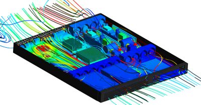
在 Ansys Icepak 電子冷卻模擬軟體中,包含強制空氣冷卻的電腦伺服器典型電子散熱分析
相關資源
讓我們開始吧
如果您面臨工程挑戰,我們的團隊將隨時為您提供協助。憑藉豐富的經驗和對創新的承諾,我們邀請您與我們聯絡。讓我們共同合作,將您的工程障礙轉化為成長和成功的機會。立即與我們聯絡,開始對話。