Synopsys and Ansys power the future of innovation—connecting silicon to systems.
-
-
学生向け無料ソフトウェアにアクセス
Ansysは次世代の技術者を支援します
学生は、世界クラスのシミュレーションソフトウェアに無料でアクセスできます。
-
今すぐAnsysに接続!
未来をデザインする
Ansysに接続して、シミュレーションが次のブレークスルーにどのように貢献できるかを確認してください。
無料トライアル
製品およびサービス
リソースとトレーニング
当社について
Back
製品およびサービス
ANSYS BLOG
April 1, 2019
How to Design an Antenna Array for 5G Networks & Applications
The world is bubbling with talk of 5G networks. Experts say that this next generation of wireless communication technology will come with lower latency, faster data rates and an explosion of connected devices.
Engineers will need to completely redesign antenna arrays so they can handle the increased bandwidth of 5G networks.
With the help of Ansys HFSS, these engineers can create 5G antenna array designs in 8 steps. HFSS can also help engineers optimize the antenna’s properties, like:
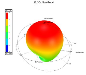
A 3D polar plot of an antenna created using HFSS
- Gain — the direction in which the signal is strongest.
- Beam steering — the ability to steer the signal to a direction.
- Return loss — the amount of energy that is reflected to a source from an antenna.
- Side lobe level — unwanted directions where the signal is sent.
At the end of the design process, engineers will have a steerable antenna array with a boosted, focused gain and minimal return loss and side lobe levels.
STEP 1: Find an Antenna Unit Template Using the HFSS Antenna Toolkit
The first step to creating an antenna array for 5G applications is to come up with an antenna unit template using the HFSS Antenna Toolkit. This antenna unit will define a single section that will eventually be duplicated into an array of antennas — hence antenna array.
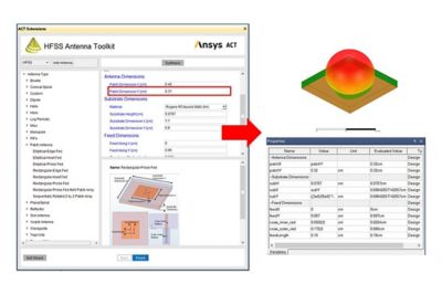
The HFSS Antenna Toolkit provides engineers with an antenna unit for their array designs.
Engineers need to choose an antenna family from the tool kit’s library. They then need to input the operating frequency and the properties of the antenna’s substrate.
A few minutes later, the toolkit will supply the engineer with the starting geometry of the antenna unit. HFSS will also calculate the antenna unit’s gain and return loss.
STEP 2: Bring the Antenna Unit into an Antenna Array
Once engineers have an antenna unit, the next step is to bring it into a periodic array. Placing the unit into an array of duplicates will help boost the gain.
In the first step, the antenna unit was assessed on its own. Now the process is repeated with a periodic element of an infinite antenna array.
Engineers will notice that properties like the gain, return loss, side lobe and beam steering are all affected by the proximity of the other antennas in the array. By changing the orientation of the antennas, engineers can optimize these properties.
Once an optimal antenna array orientation is selected, engineers can define the array factor which modifies the infinite array into an idealized finite array.
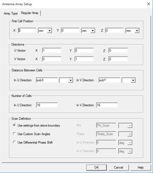
This menu is used to set up the antenna array.
In this example a 16 by 16 square antenna array is simulated.
STEP 3: Design a Finite Antenna Array Using Doman Decomposition Method
Engineers need more than idealized models to design 5G antenna arrays. As a result, the next step is to build a simulation that better describes how the antenna’s units interact with each other and the edge of the array.
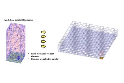
The mesh of a single antenna unit is stitched together with adjacent
antenna units within the array geometry.
This simulation is done using the domain decomposition method (DDM). DDM replicates the mesh of a single element and applies it to the geometry defined in the second step. The borders of each mesh are stitched together with adjacent meshes so engineers can assess the coupling of nearby antenna array units.
For those with access to high-performance computing (HPC), DDM is able to distribute the computational loads of each antenna unit mesh so they are solved in parallel using multiple cores.
Once the mesh is created, HFSS can be used to assess and optimize the antenna’s gain, return loss, side lobe and beam steering with more accuracy than in step 2.
STEP 4: Calculate the Beam Angle of the Finite Antenna Array
An antenna is of little use if engineers can’t control where the signal goes. These engineers can use HFSS’ Finite Array Beam Angle Calculator to determine the phase shifts needed to steer the beam to a specific direction based on the signal frequency and scan/phase angles. These angles will be used to position the array in spherical coordinates.
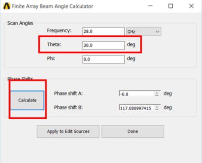
The finite array beam angle calculator
The calculator determines the relationship between the antennas in the array and the specific scan angles of the beam, based on the mesh created in the third step.
STEP 5: Design the Antenna Array’s Circuit
The next step is to design how power will be distributed across the array.
Engineers first need to decide on a target phase relationship and amplitude. They then design and iterate the power feed network, within HFSS, until they achieve this goal.
As the engineers iterate the antenna array’s power distribution circuit, they can see how each iteration affects the amplitude and phase relationship.
Once they have hooked up each array and optimized the setup, they can start to connect all their work together into one simulation.
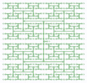
An antenna array’s power feed network
STEP 6: Connect All Antenna Array Models into One Simulation
Now engineers are able to hook up the finite element model (created in the third step) with the beam angle calculations (of the fourth step) and the power feed network (of the fifth step).
Phase shifters are also added to control the signal. The phase shifters are selected from a library of components based on the phase angles calculated in the fourth step.
Next, engineers can perform a linear network analysis (LNA) to assess the return loss for this nearly completed simulation.
STEP 7: Push the Antenna Array Excitations to HFSS
Engineers now need to push the excitation results from the LNA into HFSS. In other words, the mismatch of losses from the feed network are passed to HFSS as magnitude and phase values. The results are then plotted as a system gain.
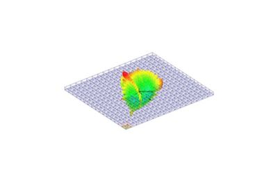
A realistic representation of an antenna array’s system gain
This gain is a more realistic reflection the antenna’s performance in all directions.
STEP 8: Test the 5G Antenna in Its Environment
The final step is to evaluate the performance of the antenna design within the context of its environment.
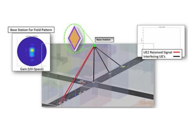
System level simulation tests the ability of the antenna to send and
receive signals within a city block.
To do this, they have to perform a system level study using HFSS shooting and bouncing ray (SBR) technology. This study tests the antenna’s ability to send and receive signals within a large environment — such as a city block.
To learn more, download the white paper, How to Design Base Station (or Microcell) Antenna Arrays for 5G Wireless Networks.