Synopsys and Ansys power the future of innovation—connecting silicon to systems.
-
-
Software gratuito per studenti
Ansys potenzia la nuova generazione di ingegneri
Gli studenti hanno accesso gratuito a software di simulazione di livello mondiale.
-
Connettiti subito con Ansys!
Progetta il tuo futuro
Connettiti a Ansys per scoprire come la simulazione può potenziare la tua prossima innovazione.
Customer Center
Supporto
Partner Community
Contatta l'ufficio vendite
Per Stati Uniti e Canada
Accedi
Prove Gratuite
Prodotti & Servizi
Scopri
Chi Siamo
Back
Prodotti & Servizi
Back
Scopri
Ansys potenzia la nuova generazione di ingegneri
Gli studenti hanno accesso gratuito a software di simulazione di livello mondiale.
Back
Chi Siamo
Progetta il tuo futuro
Connettiti a Ansys per scoprire come la simulazione può potenziare la tua prossima innovazione.
Customer Center
Supporto
Partner Community
Contatta l'ufficio vendite
Per Stati Uniti e Canada
Accedi
Prove Gratuite
ANSYS BLOG
June 23, 2021
How to Mesh and Simulate Welds with Ansys Mechanical
In our previous blogs, The Fundamentals of FEA Meshing for Structural Analysis and Solver-Based Meshing: How to Maintain a High Quality Mesh, we covered what finite element analysis (FEA) meshing is, types of meshing methods and why a good quality mesh is important for the accuracy of your simulations.
Let’s use the motorcycle frame example from that blog again. Using different meshing strategies where welds or bolted connections are located on your geometry allows you to create a more refined mesh in certain locations instead of the entire model, which may take longer to solve. In this blog, we will discuss weld meshing and why it is important to have a good quality mesh for a weld analysis.
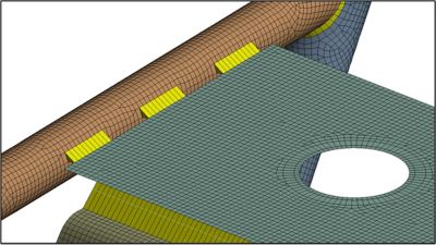
Motorcycle frame geometry shows different types of welded connections.
Element Types Used in Welded Structures
Welds are a convenient fabrication process used that uses heat to connect multiple parts by melting material in a localized region and fusing the base metals being joined. Welds are common in both thick cast parts like engine blocks and thin-walled parts like frames in automobiles.
Simulation is a widely used and a well-established method to analyze the strength and durability of these welded structures. Careful attention to the meshing of welds allows you to accurately compute the useful life of welds and represent rigidity of structure for crash or noise, vibration and harshness (NVH) analysis.
For analysis of welded structures, a mix of solid, shell and beam elements are typically used.
While solid elements can be used to model bulky parts manufactured by casting and forging processes, shell and beam elements are convenient to represent thin-walled geometries manufactured by sheet metal forming, rolling and drawing operations. By linking change in curvature in beam and shell elements to strains, thin sections can be conveniently represented by smaller sized – yet highly accurate – models.
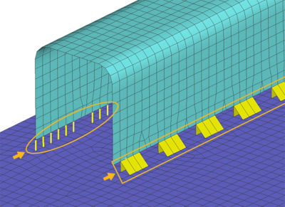
Welds simulated as shell elements (right) and welds simulated as beam elements (left).
Meshing and Simulating Welds
Using Structured vs. Unstructured Mesh to Simulate Welds
Meshing technology for complex, thin-walled geometries has advanced significantly and has made structured meshes possible – even for complex geometries. In several applications, the deformation pattern and change in strain values have a preferred direction making structured meshes preferable.
Structured meshes are convenient because you obtain an accurate, mesh-size independent solution with relatively larger elements when compared with unstructured meshes. This is particularly useful when you evaluate the life of individual welds.
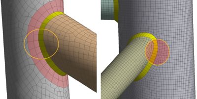
Structured (left) vs. unstructured (right) mesh shown on welded geometry.
Why Simulating Welds is Challenging
A particular challenge in the analysis of welded structures is in the creation and meshing of welds for analysis. For example, a typical automotive frame structure could contain a few thousand individual spot welds, while the chassis structure of an off-road vehicle could contain several dozen seam welds.
Ansys Mechanical has enables users to create and model spot and seam welds in an efficient, automated manner. Users can create spot weld connections rapidly by bringing in locations of welds from computer-aided design (CAD) systems. This includes the ability to control the rigidity of individual welds for accurate representation. Convenient meshing tools enable you to create seam welds with appropriate mesh patterns at weld root locations and heat-affected zone areas, which are critical to predict fatigue life.
The Importance of Mesh Quality and Life of Welds
Welded structures are subjected to a variety of loading conditions, including harmonically or randomly varying loads, tanks being pressurized and depressurized, car chassis subjected to acceleration, braking and road bumps.
When evaluating the life of welds under such fatigue loads, one must account for the welding process that alters base material properties. Rapid cooling of the weld pool can increase the hardness, though with lower ductility. Impurities during the welding process can also be detrimental to the strength of individual welds. For accurate life prediction, you also need to account for the above and any residual strains in the base material after the welding process.
Maintain heat affected zones in weld connections for fatigue calculations.
These factors can be considered during computation of the life of welds using the fatigue tools. Because the life prediction is sensitive to the stress gradients at the weld heat affected zone, it is essential that the mesh is appropriately sized in this region.
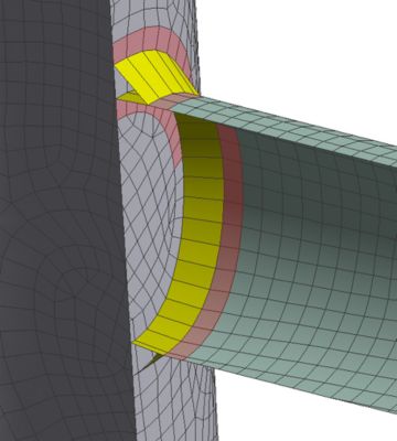
A structured quadrilateral mesh is ideal in these types of situations. It is suited to capture the peak stress at the weld toe and the steep stress gradient around the region. While a regular-shaped, graded mesh size is ideal for evaluating durability of welds, the requirements are different for crash safety analysis. Here, a uniform-sized mesh is preferred for computational efficiency.
A poorly graded mesh size could increase the solution time of the explicit solver. For both crash and NVH analysis, the accurate representation of weld stiffness is the most important. This is essential for accurate computation of the energy absorption by the structure under dynamic crash loads or natural frequency modes in modal and harmonic analysis.
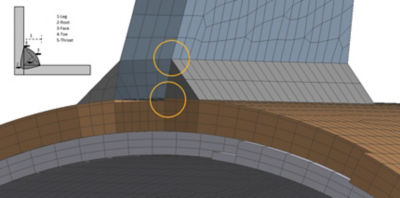
Seam welds simulated with hex elements to maintain weld root and toe locations.
Ansys Mechanical has a distinct advantage permitting parametric design of welded structures. The ability to automatically regenerate welds with design changes greatly improves productivity. The convenience of generating meshes with minimal settings for crash, durability and NVH workflows, together with seamless connectivity to Ansy nCode DesignLife for computing fatigue life, makes for a powerful user experience.
Learn more in our on-demand webinar FEA Preprocessing Productivity Improvements by Ansys Mechanical.
You may also take the Ansys Explicit Dynamics Course on the Ansys Learning Hub.