Synopsys and Ansys power the future of innovation—connecting silicon to systems.
-
-
Access Free Student Software
Ansys empowers the next generation of engineers
Students get free access to world-class simulation software.
-
Connect with Ansys Now!
Design your future
Connect with Ansys to explore how simulation can power your next breakthrough.
Free Trials
Products & Services
Learn
About
Back
Products & Services
Back
Learn
Ansys empowers the next generation of engineers
Students get free access to world-class simulation software.
Back
About
Design your future
Connect with Ansys to explore how simulation can power your next breakthrough.
Free Trials
TOPIC DETAILS
What is Multibody Dynamics?
Most machines contain multiple parts. Products like robots, industrial equipment, automotive suspensions, and medical devices are built from structures connected by joints and moved by motors and actuators. Multibody dynamics (MBD) is a subset of numerical simulation that models the dynamic behavior of mechanical systems consisting of interconnected parts, accounting for momentum, contact, and acceleration.
Engineers integrate multibody dynamics simulation into their product development and product life cycle management processes because multibody systems are complex, and the components in the system interact in complex ways. For example, to size a motor for an industrial machine, engineers need to know how much torque is required to overcome gearbox losses, friction at joints, external forces acting on the parts, and the components' momentum.
An MBD model is also much more efficient, solving in almost real time, compared to a full, high-fidelity representation such as a finite element analysis (FEA) model. Within a given industry, the mechanisms used are often similar, so many MBD software packages also include application-specific tools to speed up model building and help users obtain accurate, actionable information about their products earlier in the design process.
Important Definitions Related to Multibody Dynamics Simulation
Before looking into specific applications and recommendations for using MBD simulation, it’s a good idea to understand some basic definitions within multibody dynamics, beginning with the governing equation of motion, physical characteristics, and the contents of an MBD model.
Equation of Motion
An MBD model is a mathematical representation of Newton’s equations of motion, F = ma (force = mass*acceleration), converted into a transient dynamic form to take into account the behavior of each body in a system:
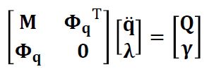
M = The system mass matrix.
q = The generalized coordinates, or locations of the system.
\( \Phi_{q} \)= The constraint Jacobian matrix that relates the system’s constraints to the generalized coordinates of the system.
\( \Phi_{\tau}^{q} \) = The transpose of the constraint Jacobian matrix.
The Unknowns Vector (the values that the solver calculates):
q̈ = The generalized accelerations of the bodies in the system.
\( \lambda \) = The Lagrange multipliers as a vector representing the constraint forces. These are the unknown forces and torques on the connections between bodies.
Force and constraint vector (right-hand vector):
Q = The generalized applied forces, including gravity, spring and damper forces, actuator and motor forces, and Coriolis and centrifugal forces.
\( \Upsilon \)= The acceleration constraints, including velocities and fixed positions.
Industrial Applications for Multibody Dynamics Simulation
Many industries produce products that are multibody systems, consisting of components that move relative to one another and transmit forces between bodies. Below are five real-world examples where mechanical engineers use MBD simulation to understand the system dynamics of the products they design and maintain.
Industrial Machinery
Complex mechanisms drive many manufacturing and material-processing machines, so mechanical engineers who design them rely on multibody dynamics simulation. Engineers use MBD models to virtually prototype functionality. They will use their model to make sure parts don’t make unwanted contact, size motors and actuators, and calculate cyclical loads on components to estimate fatigue. They also use their models to optimize the system's efficiency, adjusting input parameters and geometry to increase throughput. Engineers can also connect their control software to their MBD model to do virtual testing of the entire system.
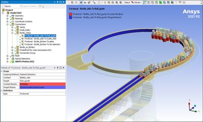
An example of a bottle sorting system modeled in Ansys Motion multibody dynamics simulation software.
Automotive Suspensions
Cars are full of mechanisms that benefit from MBD simulations. In fact, automotive engineers were among the first to use the multibody simulation approach. Automotive suspensions, with complex linkages containing springs and dampers designed to absorb and smooth out the dynamic loads of driving on rough roads, are ideal for multibody dynamics. This type of simulation has become an essential part of automotive noise, vibration, and harshness (NVH) studies to deliver a pleasurable experience to drivers and passengers.
Spacecraft
MBD simulation is a critical tool for aerospace engineers designing spacecraft because they can’t easily test the movement and loads of such systems in zero gravity on Earth. Some common examples include the gimbal that adjusts the thrust direction of a rocket motor, the deployment mechanism of a solar panel, and the motors and valves used in liquid engines or cooling systems.
Robotics
Robots may be the most direct real-world representation of multibody dynamic systems. They consist of rigid bodies connected by joints and driven by motors and linear actuators. Many robotic programming systems have built-in MBD solvers to make accurate simulation part of the programming workflow. As with industrial machinery, the goal of multibody dynamics simulation is to detect possible collisions, calculate loads, determine fatigue life, and optimize speed.
An animation of a robot modeled in Ansys Motion multibody dynamics simulation software.
Biomechanics
Our own bodies are also great examples of dynamic multibody systems. Our muscles act as actuators that pull on tendons that move bones around joints and allow rotation about one (knuckle), two (wrist), or three axes (hip). Biomedical engineers use MBD simulations to optimize an athlete’s performance, artificial joint design, and medical device design for physical therapy or to hold parts of the body rigid to aid recovery from breaks and sprains.
Multibody Dynamics Simulation Physical Characteristics
Here is a list of the most commonly used terms to describe the physical characteristics of multibody dynamics models.
- Degree of Freedom: The position and orientation of a point in the model. A rigid body in 3D spacehas six degrees of freedom: the three translations along the three axes (x, y, z) and the three rotations about the three axes (rotx, roty, rotz).
- Kinematics: The description of linear and rotational motion without taking forces, and therefore mass and momentum, into account.
- Dynamics: The description of motion over time, taking forces, and therefore mass and momentum, into account.
- Mass: An object's resistance to linear acceleration.
- Moments of Inertia: An object's resistance to angular acceleration.
- Center of Mass: The average position of the mass in an object. It represents a single point where all the mass concentrates.
- Mass Properties: The mass, moments of inertia, and center of mass of a body.
- Dynamic Forces: The external and internal applied forces acting on the objects in the system. Examples of dynamic forces include gravity, springs, dampers, actuators, motors, and friction, as well as Coriolis and centrifugal forces. In some cases, as with damping or a spring, the force can depend on the object's position or velocity.
- Constraint: A defined value for the position, velocity, or acceleration of a degree of freedom.
- Constraint Equations: A formulation relating the position, velocity, or acceleration of two or more degrees of freedom.
Multibody Dynamics Simulation Modeling Terms
Engineers use the following terms to describe different parts of their MBD models.
- Rigid Body: An idealized object that doesn’t deform when a load is applied. A mathematical way to look at a rigid body is that the distance between any two points never changes.
- Flexible Body: An object that deforms when a load is applied. MBD tools use several different algorithms to represent this flexibility in a simplified or a detailed way.
- Connections: A relationship between two objects defining the relative motion (joints) or forces (control devices) between bodies in the model.
- Joints: A connection between two objects that specifies constraints between degrees of freedom. For example, a revolute joint allows rotation about a single axis, but no relative translation and no rotation about the other axis.
- Control Devices: An algorithm that defines a force between two bodies or a body and the ground. A control device can be a motor, actuator, damper, gears, or spring.
- Boundary Conditions: A defined motion in the form of a position, velocity, or acceleration.
- Nodes: A point in the model where the solver calculates equations and solutions for connections, forces, displacements, and rotations.
- Loads: An internal or external force or torque acting on an object.
- Contact: The interaction of two bodies when they touch, and contact forces transfer between them. In a dynamics analysis, a contact specification keeps one body from penetrating another.
- Sensors: A simulated device in the model that measures and reports a physical characteristic in the model. Examples include the distance between two nodes, the reaction forces and torques at a joint, and the linear and rotational positions, velocities, and accelerations of a body. Sensors are also used during a simulation to compute values used by control devices to calculate loads.
Suggestions for Driving Designs with Multibody Dynamics Simulation
Any system containing mechanisms can benefit from multibody dynamics simulation during the design process. It could be a simple kinematic study to make sure everything moves properly, or a complex nonlinear dynamics simulation with contact, non-linear springs, and complex stepper motor control software.
The most important recommendation for success in MBD modeling is choosing a robust, accurate, and fast general-purpose MBD tool like Ansys Motion multibody dynamics simulation software. Selecting a tool that is easy to use, integrates with CAD, and offers advanced capabilities won’t limit product simulation abilities.
Taking time to plan the model is also important. The following steps are a good start to document what is needed to create a valuable and robust MBD simulation:
- Decide what the goal of the MBD model is
- Map out the assembly
- Identify rigid and flexible bodies
- Determine what methods the flexible bodies should represent
- Define the joints and control devices
- Place sensors to pull information during and after solves
It is also good to check if the selected MBD simulation software has any application-specific workflows that make setting up and post-processing models much easier. As an example, Ansys Motion software includes applications like the Drivetrain Toolkit, Car Toolkit, and Links Toolkit for modeling chains, belts, and tracks.
MBD models can also support system-level simulation in a tool like Ansys Model Center model-based systems engineering software, by connecting it to the MATLAB/SIMULINK control model, or creating reduced-order models in Ansys TwinAI digital twin software.
Related Resources
Let’s Get Started
If you're facing engineering challenges, our team is here to assist. With a wealth of experience and a commitment to innovation, we invite you to reach out to us. Let's collaborate to turn your engineering obstacles into opportunities for growth and success. Contact us today to start the conversation.