Synopsys and Ansys power the future of innovation—connecting silicon to systems.
-
-
Access Free Student Software
Ansys empowers the next generation of engineers
Students get free access to world-class simulation software.
-
Connect with Ansys Now!
Design your future
Connect with Ansys to explore how simulation can power your next breakthrough.
Free Trials
Products & Services
Learn
About
Back
Products & Services
Back
Learn
Ansys empowers the next generation of engineers
Students get free access to world-class simulation software.
Back
About
Design your future
Connect with Ansys to explore how simulation can power your next breakthrough.
Free Trials
ANSYS BLOG
October 9, 2023
Accelerate Hydrogen Adoption Using Simulation
Hydrogen is an important element of cleaner technology to accelerate the ongoing energy transition and meet the decarbonization goals of several countries. Hydrogen can play a dual role in the global decarbonization mission as an energy storage medium for integrated energy systems and as a cleaner fuel for mobility, heavy industry (e.g., iron and steel, chemicals, cement, etc.), aviation, maritime shipping, and other industries
While the overall focus of the hydrogen economy is on the full hydrogen value chain — which includes hydrogen production, storage and transportation, and utilization (or consumption) — understanding the utilization part is important in the short term and will impact the entire hydrogen ecosystem. The amount of hydrogen demanded in 2021 was around 94 million tonnes according to the International Energy Agency’s (IEA) Global Hydrogen Review1. Hydrogen can be used directly in fuel cells, gas turbine engines, internal combustion engines, or in furnaces as a carbon-neutral fuel or as feedstock to produce storage-friendly derivatives. These derivatives include ammonia, methanol, or sustainable aviation fuels (SAF) that are used in specific industrial and transport applications.
Let’s get an understanding of the combustion characteristics of hydrogen that will be handy in addressing the key challenges of using hydrogen as a fuel.
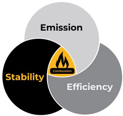
Figure 1. Optimization of emission, stability, and efficiency of combustion is critical.
Optimization of the combustion process is a balancing act of three critical metrics: efficiency, emission, and stability. While achieving a higher temperature during a combustion process is better from the efficiency and stability point of view, it poses challenges for emissions — mainly nitric oxide (NOx) — and metal protection. On the other hand, achieving lower combustion temperature is better for emissions and surrounding metal protection, but it typically results in lower efficiency of the combustion process and creates issues for the combustion stabilities. Therefore, part of the design of the combustion device is the art of achieving a balance among the efficiency, emission, and stability of the combustion. These parameters are also governed by the fuel's characteristics, for example, its flame speed, flammability limit of the combustion, and energy required for ignition of a given fuel.
The characteristics of hydrogen as a fuel are:
- It has 8 times higher flame speed than typical hydrocarbon.
- Its flammability limit in the air is 4% to 70% by volume, which is wider than hydrocarbons.
- It requires 15 times lower ignition energy than hydrocarbons.
These three characteristics of hydrogen enable the achievement of better efficiency and stability of combustion. Furthermore, the absence of carbon molecules in hydrogen combustion makes it attractive from the carbon-neutral emission point of view as well. However, as they say, there is no free lunch. The higher flame speed and wider flammability limit of hydrogen pose key challenges to flashback and other safety-related issues. The higher flame temperature in hydrogen flames poses challenges for NOx and metal protection. Another typical characteristic of strong differential diffusion of hydrogen due to its lower Lewis number, is a major concern for combustion instabilities. The differential diffusion leads to variations of the local equivalence ratio and, hence, reaction rates along the flame front. Therefore, the adoption of hydrogen as a cleaner fuel at a large scale depends on how quickly the issues related to flashback, NOx emission, and combustion instabilities are addressed.
The Role of Simulation in Understanding Hydrogen Combustion
Computation fluid dynamics (CFD) simulations are an integral part of the ongoing research on pure hydrogen or hydrogen-blended fuel combustion to accelerate the adoption of hydrogen as a cleaner fuel. Simulations can help to understand the flame characteristics and dynamics at different operating conditions (operating pressures, flow rates, stabilization mechanisms, burner geometrical variations), different blend ratios, and other factors. These insights will help to overcome the challenges of flame flashback, NOx, and combustion instabilities associated with hydrogen combustion.
Developing Confidence in the Simulation Results
While simulations can aid researchers in mitigating the challenges related to hydrogen combustion, the accuracy of the results predicted using simulation depends on the combustion model, the reaction mechanism, the mesh resolution in the flame region, the solution methodology and approach, and several other factors. These factors need to be studied and validated for the range of flames having different compositions, stabilization mechanisms, and flame characteristics. Ansys has been actively engaged in developing a set of validation cases that can easily be used as a quick reference guide.
Let’s look at eight different flames that represent the subset of behavior observed in actual hydrogen combustion systems:
- SMH1 flame: Swirl stabilization study
- HM3e flame: Blow out study
- Cabra hydrogen lifted flame: Blow out study
- SimVal flame: Study of flashback
- TUBerlin flame: Study of flashback
- DLR jet in crossflow flame: Flame stabilization study
- KAUST ammonia flame: Flame stabilization study
- Hylon flame: Flame stabilization study
SMH1 burner

TUBerlin flame
HM3e burner
DLR JICF flame

Cabra H2 flame

KAUST NH3 flame

SimVal flame

Hylon flame
Figure 2. Different hydrogen/hydrogen-blended flames
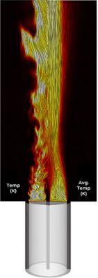
SMH1 Burner
Swirl-stabilized flames are extensively studied due to their wider applications in gas turbine industries. A swirl-stabilized flame from the Sydney experimental database, SMH1,2 provides rich test data on flame characteristics that can be compared with CFD simulations. SMH1 flame has a fuel jet at the center with methane (CH4 and hydrogen (H2 in a 1:1 ratio by volume, surrounded by a bluff body. A swirling flow of air is introduced through the annulus, outside the bluff body. The flame is operated in a stable condition, with considerable stretching and rapid air entrainment. A comparison of flame structures like the recirculation zone near the bluff body (a body that causes a separation of flow around it because of its shape), necking zone, and jet-like zone for this flame as shown in Figure 3 are well-predicted using Ansys Fluent
Figure 4. Animation of temperature field for SMH1 flame
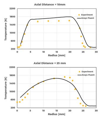
Figure 3. Radial temperature profile of SMH1 flame at different axial planes
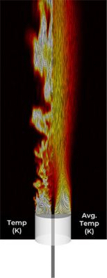
HM3e Burner
Bluff body stabilized flames are also extensively studied due to their similarities with many industrial applications. As they include some of the complications associated with practical combustors while maintaining simple and well-defined boundary conditions, they are ideal for the study of turbulence-chemistry interaction. Study on bluff body stabilized HM3e2 burner, using CH4 and H2 in 1:1 ratio by volume as fuel stream is performed using Fluent. The fuel jet velocity is 90% of the velocity at which a complete flame blowout occurs. As a result, flames experience high local extinction events associated with strong finite-rate chemistry effects. Results from the study are shown in Figure 5. As the mixing intensifies (x > 13mm), the extinction in the flame due to large-scale vortex breakdown is seen in the plots. Overall agreement with experiments is seen, both qualitatively and quantitatively.
Figure 6. Animation of temperature field for HM3e flame
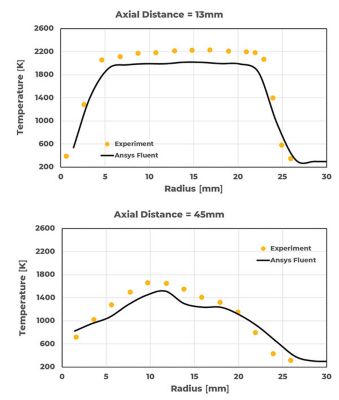
Figure 5. Radial temperature profile of HM3e flame at different axial planes
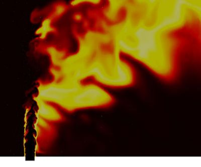
Cabra H2 Flame
Figure 7. Animations of flame lift-off sensitivity to co-flow temperature for Cabra hydrogen lifted flame
Cabra flame configuration provides a method to study the coupling of turbulent mixing and chemical kinetics, removing the complexity of recirculation regions often present in combustors. The turbulent lifted hydrogen/nitrogen (H2/N2) jet flame in a vitiating co-flow environment is studied using Fluent3. Due to the hot vitiated H2/air co-flow, the primary stabilization mechanism is the autoignition followed by a premixed flame. As shown in the results in Figure 7, Fluent successfully captured the variation of flame lift-off length with a change in co-flow temperatures for all simulated test points.
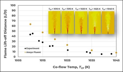
Figure 8. Flame lift-off distance of Cabra hydrogen lifted flame with different co-flow temperature
SimVal Flame
In addition to stabilization of flame, study of flame flashback is critical for H2/H2-blended combustion. There are several mechanisms of flashback like boundary layer flashback, combustion-induced vortex breakdown, turbulence in the flow, fluctuations in equivalence ratio, etc. Prediction of flashback requires accurate modeling of highly transient chemistry phenomena and the impact of heat loss on chemistry. The configuration of the swirl stabilized combustor (SimVal) from the National Energy Technology Laboratory is used to evaluate flashback predictivity by Fluent.4 Results from the study are shown in Figure 9. Range of CH4 and H2 blends are tested for the premixed swirling air/fuel system with the equivalence ratio of 0.6. Simulations are able to predict the correct composition of the CH4-H2 blend that triggers the onset of flashback.
Figure 9. Animation of flame flashback with blend ratio of CH4:H2 (by volume)
TUBerlin Flame
Pure hydrogen premixed swirl stabilized flame configurations with axial injection to influence the vortex breakout and thus prevent flashback is extensively tested at the University of Berlin (TUBerlin). Simulations5 are performed to predict the flame position and characteristics and the results are compared with the test data. Results are shown in Figure 10. As we see, the flow structure and flame region simulated using Fluent compare well with the test results.
Figure 10. Animation of flame shape for TUBerlin flame
DLR JICF
Jet-in-cross flow (JICF) is another configuration that is extensively being studied due to its ability to avoid flashback as well as provide better control of hydrogen combustion. Fluent’s performance is evaluated for DLR JICF6 configurations at high-pressure values of 15 and 10 bar to understand the predictability of flame structures as a function of H2 concentration in the jet stream. As shown in Figure 11, simulations predicted the correct trend of flame attachment in the upstream region for different H2 and CH4 blend ratios and operating pressures, which are found to be strong functions of species diffusion and resolution of jet interactions.

Case-1: 40% H2 | Pressure = 10 Bar

Case-2: 20% H2 | Pressure = 10 Bar

Case-3: 40% H2 | Pressure = 15 Bar

Case-2: 20% H2 | Pressure = 15 Bar
Figure 11. Flame shape for different blend ratios at different operating pressures (DLR-JICF)
HYLON Flame
Hydrogen air flames are extensively studied using the HYdrogen LOw NOx (HYLON)7 dual swirl injector. The inner injector of this assembly consists of an axial swirler of helical shape and supplies hydrogen. Whereas swirling airflow is supplied through the annular channel. Results related to the attached flame (Flame A) and lifted flame (Flame L) are shown in Figure 12. Flame-A is anchored on the hydrogen injector lips, whereas Flame-L is lifted above the injector. Getting a consistent flame pattern corresponding to operating conditions A and L is challenging. As shown in the figure, Fluent is able to predict the correct flame shapes with changes in operating conditions.
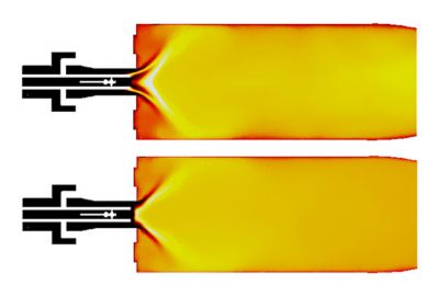
Figure 12. Flame A (top) and L (bottom) correspond to different operating conditions of the HYLON burner
KAUST Ammonia Flame
Ammonia (NH3) is gaining importance as a standalone carbon-free fuel species as well as a carrier of hydrogen for combustion systems. Pure NH3 combustion is challenging because of low reactivity and emission of nitric oxides. Hence an alternate method of utilizing cracking of NH3 into H2 and N2 before combustion is often used. Experimental data from KAUST8 available for a bluff body stabilized flame operating under different combinations of NH3, H2, and N2 (representing different levels of cracking), are analyzed through simulations. As shown in Figure 13, Fluent can predict key flame characteristics with the increase in the cracking ratio, like flame elongation with the increase in the cracking ratio, which is characterized by a more stable flame with reduced thermal radiation. Fluent can also be used to analyze the shift of the burning region from the outer shear layer to the inner layer next to the jet due to higher momentum flux (jet/co-flow), since the Reynolds Number (Re) is kept constant.
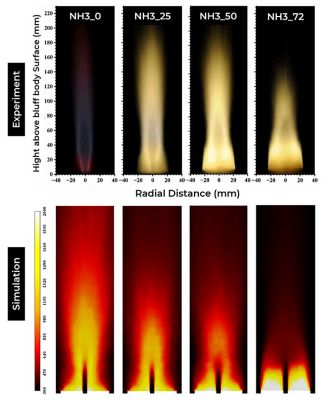
Figure 13. Change in flame shape with the increase in cracking ratio (represented H2-N2 percentage, KAUST Flame)
Accelerating Hydrogen R&D With Simulation
Given the fact that today hydrogen combustion has gained the highest focus in its history, mitigating the associated challenges like flame stability, flashback, NOx emissions, etc. is a key to its successful adoption for large-scale use in global decarbonization efforts. Ansys is committed to supporting its customers to accelerate their research and development through simulations for meeting the net zero targets.
References:
- International Energy Agency (IEA), Global Hydrogen Review 2022
- Verma, I, Yadav, R, Shrivastava, S, & Nakod, P., GT2022- 82583. Proceedings of the ASME Turbo Expo 2022: Turbomachinery Technical Conference and Exposition. Volume 2: Coal, Biomass, Hydrogen, and Alternative Fuels; Controls, Diagnostics, and Instrumentation; Steam Turbine. Rotterdam, Netherlands. June 13–17, 2022. V002T03A012. ASME
- Xia, Y, Verma, I, Nakod, P, Yadav, R, Orsino, S, & Li, S., GT2022-80733. Proceedings of the ASME Turbo Expo 2022: Turbomachinery Technical Conference and Exposition. Volume 2: Coal, Biomass, Hydrogen, and Alternative Fuels; Controls, Diagnostics, and Instrumentation; Steam Turbine. Rotterdam, Netherlands. June 13–17, 2022. V002T03A004. ASME
- Verma, I, Yadav, R, Ansari, N, Orsino, S, Li, S, & Nakod, P., GT2022- 82601. Proceedings of the ASME Turbo Expo 2022: Turbomachinery Technical Conference and Exposition. Volume 3B: Combustion, Fuels, and Emissions. Rotterdam, Netherlands.
- M. Amerighi∗, P. C. Nassini, A. Andreini, S. Orsino, I. Verma, R. Yadav, S. Patil., GT2023-102651. Proceedings of ASME Turbo Expo 2023 Turbomachinery Technical Conference and Exposition GT2023 June 26-30, 2023, Boston, MA
- Pankaj Saini, Ianko Chterev, Jhon Pareja, Manfred Aigner & Isaac Boxx, Flow Turbulence Combust 105, 787–806 (2020).
- TNF Workshop, International Workshop on Measurement and Computation of Turbulent Flames
- Adamu A., Ayman M. E., Jiajun L., Suliman A., Hong G. Im, Bassam D., Combustion and Flame, Volume 258, Part 2, 2023,