-
-
学生向け無料ソフトウェアにアクセス
Ansysは次世代の技術者を支援します
学生は、世界クラスのシミュレーションソフトウェアに無料でアクセスできます。
-
今すぐAnsysに接続!
未来をデザインする
Ansysに接続して、シミュレーションが次のブレークスルーにどのように貢献できるかを確認してください。
国および地域
無料トライアル
製品およびサービス
リソースとトレーニング
当社について
Back
製品およびサービス
ANSYS BLOG
November 11, 2016
Importing ECAD Trace Data for Better Thermal and Vibrational Analysis
Many of our customers are reaping the benefits of the trace import functionality in Ansys Mechanical, which accounts for the effects of copper distribution on every layer of a printed circuit board (PCB) — or printed circuit board assembled (PBA) — for your thermal stress analysis, modal, shock and random vibration simulations. Just think — you can capture the accuracy necessary to confidently make engineering decisions in a fraction of the time you are currently spending on lumped parameter models. In this post, I’ll give you a brief overview and explanation of the process.
For those new to the idea of trace import, it is critical to highlight that the detailed traces, vias, etc. are not being meshed. Instead, it is the material properties that are being mapped onto the finite element mesh. As shown in Figure 1, this functionality is implemented by dragging and dropping external data to connect the data to the Model cell of any structural simulation. Under the hood, the trace import function performs a “rule of mixtures” calculation on the material properties based upon the fractions of metal and dielectric in each element, and then assigns this set of material properties onto each finite element. Before trace import was added, you would need to first create the PCB geometry, extract the metal fraction for each layer, and then calculate the equivalent lumped material property set. Not only was this a time consuming and tedious process, it provided a significantly less accurate solution
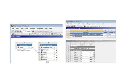
Figure 1. Screen shot of the Workbench platform Trace information is connected into a structural analysis and SpaceClaim is used for the PCB layer geometry.
Now that we have the trace information without meshing the traces, where does the PCB geometry come from? Ansys SpaceClaim. The SpaceClaim 3-D modeling software filters out all the detailed trace information and imports only the PCB layers into Ansys Mechanical. Ansys Mechanical then meshes the PCB layers and maps the spatially distributed material properties onto them.
The most common pitfall of this process is in the first step of importing the geometry into SpaceClaim: setting the Import mode to Layer Topology. The setting is in the ECAD file options of the SpaceClaim Options (available via File→SpaceClaim Options).
If you choose Layer Geometry, you will import all of the detailed trace information. Notice that in Figure 2A with Layer Topology selected, only the PCB layers are imported, whereas in Figure 2B with Layer Geometry selected, 27,238 bodies representing components, traces, vias, etc. are imported, which is nearly impossible to mesh. This is why we’re using trace import
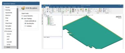
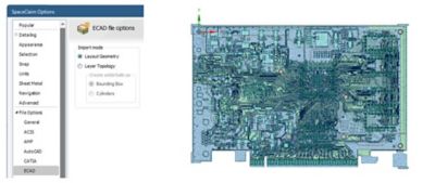
Figure 2. (A) Layer Topology selection on ECAD file options filters most details. (B) Layer Geometry selection on ECAD file options imports 27,238 bodies, which is nearly impossible to mesh.
Now that the geometry is imported into SpaceClaim, you will probably want to add components for heat sources or to study their attach integrity in a static or dynamic structural analysis. You can do this in the SpaceClaim environment. It is important to realize that the PCB must remain a multibodied component in Ansys Mechanical and contact elements are used to connect the PCB to the added components. This means in SpacecClaim that all layers of the PCB must be in its own unique component and its topology must be shared.
Even when importing the ECAD geometry with Layer Topology selected, stray components may be imported — this is included in the tutorial. Notice in Figure 3, under the STP component that the stray parts are imported under Components (STP). You can either uncheck Components (STP) and these hidden parts will not be imported into Ansys Mechanical, or right-click on Components (STP) and choose Move to New Component. Regardless of your choice, the topology of the STP component must be shared as shown in Figure 4A. This creates the multibodied part [integral mesh] of the PCB necessary for the trace import to map the material properties.
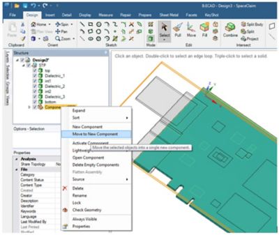
Figure 3. SpaceClaim screen capture of an imported TGZ file. The PCB layers must be contained in their own component.
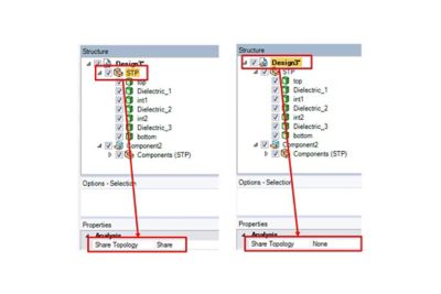
Figure 4. (A) The topology of the PCB must be shared to create a multibodied part in Ansys Mechanical.(B) If there are any other parts or components with the PCB, their topology must not be shared and contact elements in Ansys Mechanical will be used to connect them together.
Now that the PCB component has a shared topology, the trick to adding components in SpaceClaim is to first ensure the No Merge option is selected when extruding parts, and then use the ruler to locate the components off the edges of the PCB, as shown in Figure 5. Once you add components as described here, or if you opt to move Components (STP) to new components, you need to go back to Figure 4B and make sure that the topology for all these components and parts is NOT shared. Contact elements will be used to connect the PCB to these additional parts and/or components.
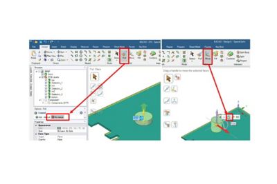
Figure 5. Tricks to adding components to PCB. Select No Merge when creating parts and use the ruler to locate the parts (for example, PCB edges).
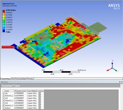
After the geometry is defined in SpaceClaim and imported into Ansys Mechanical, then the trace information is imported onto the PCB bodies. If parts in addition to the PCB have been imported, then make sure to select only the PCB bodies when scoping the imported trace, as highlighted in Figure 6. Note that multiple PCBs and their trace files can be incorporated into the same analysis; each will have its own unique external data modifier, as shown in File1 in Figures 1 and 6. Remember to assign each layer of the PCB as the dielectric (typically FR-4) under the Geometry branch of the outline tree and define the metal material under the Imported Trace as shown in Figure 6. Once the PCB is meshed and the trace information imported, the user can view the metal fraction, also shown in Figure 6.
The ECAD file formats Ansys Mechanical and SpaceClaim are capable of importing include: Cadence BRD/MCM/SIP, ODB++ [TGZ], Ansoft ANF, Icepak BOOL+INFO or COND+INFO. The example here imports an ODB++ [TGZ] file. As shown in Figure 1, you can apply a rigid body transformation if the global CS of the simulation and the ECAD file are different.
It might be useful to point out that the trace import function is the same function Ansys Icepak has had for several releases. Icepak is an Ansys module that provides best-in-class electronic cooling simulation using the Ansys Fluent solvers. You can also perform thermal analysis in Ansys Mechanical when the heat transfer is dominated by conduction. Temperature distributions from either Icepak or Ansys Mechanical can easily be mapped into Ansys Mechanical for thermal-stress analyses.
A cracked solder joint results from the glass transition effect of an acrylic conformal coating that bridges the component body and board.
If you want to learn more about trace import functionality, we have lots of additional resources for you at Ansys Structures.