Synopsys and Ansys power the future of innovation—connecting silicon to systems.
-
-
学生向け無料ソフトウェアにアクセス
Ansysは次世代の技術者を支援します
学生は、世界クラスのシミュレーションソフトウェアに無料でアクセスできます。
-
今すぐAnsysに接続!
未来をデザインする
Ansysに接続して、シミュレーションが次のブレークスルーにどのように貢献できるかを確認してください。
無料トライアル
製品およびサービス
リソースとトレーニング
当社について
Back
製品およびサービス
ANSYS BLOG
March 21, 2022
5 Best Practices for Gas Turbine Combustor Meshing
Ansys Fluent accelerates the meshing of complex geometries, like those of gas turbine combustors, to generate a high-quality mesh.
Gas turbine combustors involve complex physics and geometries that have detailed features. This can result in long turnaround times and high costs to perform CFD simulations.
Nowadays, engineers try to minimize geometry simplification for gas turbine combustors to capture more physics in a single model. That includes examining all sub-components, like:
- Atomizers
- Swirlers
- Pre-diffusers
- Effusion and dilution orifices
Modeling combustion physics creates challenges because it factors in turbulence, chemistry, combustion, emissions, spray and much more. Properly capturing the physics within the combustion process requires scale-resolving methods. Additionally, very dense meshes are required to resolve the turbulence accurately.
Having a uniform and dense mesh within the reacting zone proves difficult using traditional tetrahedral or polyhedral mesh topologies because you have little to no control over the size variations of unstructured methods.
Ansys Fluent has a patent pending technology called Mosaic mesh that solves this problem. Using Mosaic, which is one of Ansys’ five best practices for gas turbine combustor meshing, will result in a high-quality mesh that yields robust, accurate results.

A leading aircraft engine manufacturer benefited from Ansys Fluent with: 20x speed up in meshing, 30-50% reduction in solve time and more accurate results.
The five best practices for gas turbine combustion meshing using Fluent are:
- Watertight geometry workflow
- Mosaic poly-hexcore meshing with parallel scalability
- Inflation layers
- Mesh resolution per part
- Target quality metrics
To learn about these best practices in detail, read the white paper: 5 Best Practices for Gas Turbine Combustion Meshing Using Ansys Fluent. For an overview of these best practices, continue reading below.
1. Watertight Geometry Workflow
Ansys Fluent’s task-based watertight geometry workflow accelerates gas turbine combustor meshing. Ansys Fluent’s task-based watertight geometry workflow accelerates gas turbine combustor meshing.
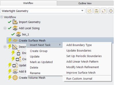
The Fluent watertight geometry workflow accelerates meshing by organizing the process into a user-friendly task-based workflow. This workflow offers relevant choices and options, but also has the flexibility to be customized.
Best practices are embedded into each task, for quality, in the form of default values. But advanced users can easily check a box to reveal more options. You can also automate the watertight geometry workflow meshing process using a python-based journal file for batch meshing.
Using this workflow will ensure a high-quality mesh that generates robust results for most gas turbine combustor cases.
2. Mosaic Poly-Hexcore Meshing with Parallel Scalability
Fluent’s Mosaic meshing technology accelerates meshing time and produces a faster, more accurate solution. This technology enables polyhedral connections between disparate mesh types. Mosaic poly-hexcore is the first to employ this technology and is a combination of hexahedral, isotropic poly prism and mosaic polyhedral elements.
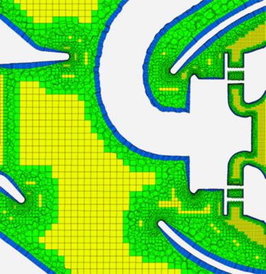
Hexahedral elements are desired because of their accuracy and efficiency. Because the core volume mesh generates using hexahedral elements, meshing for the same grid resolution results in a total face count reduction. This delivers faster compute times with lower memory and disk space requirements.
Parallel meshing can accelerate the volume meshing process even more. It has the ability to generate over 10 million cells per minute when running on 256 cores.
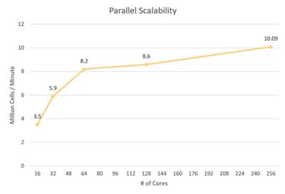
Mosaic poly-hexcore mesh can generate over 10 million cells per minute when running on 256 cores. Mosaic poly-hexcore mesh can generate over 10 million cells per minute when running on 256 cores.
3. Inflation Layers
Three inflation layers are proven to yield accurate results because Fluent uses hybrid scale resolving simulation, such as SBES, with RANS near the walls.
For gas turbine combustion simulations in Fluent, the large eddy simulation (LES) model is used in the core domain to accurately capture mixing and flame shape.

However, LES remains unable to accurately resolve the near-wall flow features without a high, and often unaffordable, mesh resolution. Therefore, Fluent uses hybrid-scale resolving simulation, such as stress blended eddy simulation (SBES). SBES uses Reynolds-averaged Navier-Stokes (RANS) near the walls and LES in the core domain.
Because of the SBES turbulence model, the third best practice suggests using three inflation layers — which has proven to yield accurate results. The same workflow could be used to generate more inflation layers if needed.
4. Mesh Resolution Per Part
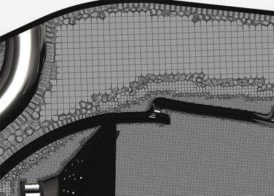
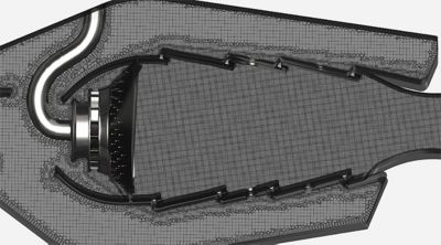
A hexahedral dominant mesh in the combustor core with coarsening in the dilution zone to reduce cell count. A hexahedral dominant mesh in the combustor core with coarsening in the dilution zone to reduce cell count.
Because of the complex features in a combustor, it is recommended to use mesh resolution best practices for the following parts:
- Swirler and atomizer
- Use around 35-45 cells depending on the length scale, across the swirler diameter to ensure a proper fuel-air mixture for accurate ignition and emission predictions.
- Combustor core
- Utilize a body of influence (BOI) to generate a high-quality uniform mesh. This will ensure a smooth mesh transition, from the dome into the core, and accurately predict mixing, flame shape and emissions.
- Dilution Holes
- Have 30-40 cells, depending on the length scale, across the diameter to accurately predict the quenching effects of the dilution holes and their placement.
- Secondary Zone (Post dilution)
- Resolution in the dilution zone can be coarser than in the primary zone. However, it is recommended to apply enough resolution to accurately capture the flow splits and to have a finer mesh near the walls to capture the heat transfer.
5. Target Mesh Quality
The quality of a mesh plays a significant role in the accuracy and stability of the numerical computation. Using the best practices listed above should result in a high-quality simulation ready mesh.
Cell orthogonal quality is computed using cell skewness, the vector from the cell centroid to each of its faces, the corresponding face area vector and the vector from the cell centroid to the centroids of each of the adjacent cells. The value ranges between zero to one — with one representing perfect quality. Target an orthogonal quality that is higher than 0.1.
Aspect ratio equates to a measure of the stretching of a cell. It remains best to avoid sudden and large changes in the cell aspect ratio in areas where the flow field exhibits large changes or strong gradients. Target a maximum aspect ratio less than 100.
For an in-depth exaplanation on each best practice, download the white paper: 5 Best Practices for Gas Turbine Combustion Meshing Using Ansys Fluent.