Case Study
Synopsys and Ansys power the future of innovation—connecting silicon to systems.
-
-
Access Free Student Software
Ansys empowers the next generation of engineers
Students get free access to world-class simulation software.
-
Connect with Ansys Now!
Design your future
Connect with Ansys to explore how simulation can power your next breakthrough.
Free Trials
Products & Services
Learn
About
Back
Products & Services
Back
Learn
Ansys empowers the next generation of engineers
Students get free access to world-class simulation software.
Back
About
Design your future
Connect with Ansys to explore how simulation can power your next breakthrough.
Free Trials
The term EMI-EMC (electromagnetic interference and electromagnetic compatibility) refers to the ability of an electronic product to operate as intended in its electromagnetic environment. Electronics and power electronics products must comply with EMI-EMC regulations, which ensure that the product does not emit excessive electromagnetic (EM) noise, classified as either conducted emissions (CE) or radiated emissions (RE) beyond a certain threshold. The product must also not be affected by the emissions from nearby equipment, which include bulk current injection (BCI) and radiated immunity (RI).
In the past, to meet the regulations, the standard industrial practice was to rely on design guidelines, testing, and engineering judgment. Further, technologists often resort to advanced simulation methods (including circuit simulations) to capture the EMI-EMC phenomenon. However, achieving accurate predictions in simulations has been challenging. By leveraging their combined strengths to advance state- of-the-art EMI-EMC simulations, collaborative efforts between Eaton and Ansys helped significantly improve capability.
Challenges
EMI-EMC emission prediction for large, complex systems involving multiple electronic boards, switching devices, enclosures, and electromechanical systems is quite challenging. Some of the key challenges are listed below.
- Significant manual effort is required in:
- Extracting a specific area of interest (of a large PCB)
- Creating numerous ports for PCB components
- Connecting a vast number of passive and active component models with their respective layout parasitic blocks
- Nonavailability of high-fidelity SPICE models for some passive, active, and custom-designed components. The dependency of these models on voltage/current biases and frequency makes it even more challenging.
- Longer runtime due to the model’s numerical size and complexity
- Convergence and stability challenges for complex systems
- Capturing interactions between subsystems of a large system that includes several electrical and mechanical components


EV DC charger
X storage — energy storage system
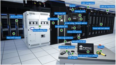
UPS and other solutions for data centers
Engineering Solutions
Ansys Electronics Desktop (AEDT)™ software offers multiple simulation tools to address the unique requirements of EMI-EMC simulations of different types of elements that are typically encountered in electronic equipment. These include PCB layouts, busbars, cables, enclosures, and power electronics devices.
AEDT software provides multiple EM solver options that are designed to address diverse challenges in capturing the electromagnetic physics associated with CE, RE, BCI, and RI simulations. Further, AEDT software provides the ability to seamlessly integrate high-fidelity mathematical subsystem blocks (generated using multiple tools) into one system-level model, thus enabling Eaton to capture critical electromagnetic interactions without loss of fidelity.
AEDT software supports automation scripting, which enables the automation of complex processes tailored to Eaton’s needs. This enables accelerated simulation setup with the least amount of manual effort for maximum analysis throughput.
While Eaton continues to deploy state-of-the-art simulation methodologies on key programs, Eaton and Ansys continue to collaborate to make simulations even more efficient and robust.
Benefits
“Analysis First” is a key pillar in Eaton's digital transformation strategy, and EMI-EMC simulations using AEDT software are a critical addition to their portfolio of niche, cutting-edge capabilities. Some of the key benefits of leveraging EMI-EMC advanced simulation capabilities are below.
- These advanced capabilities enabled Eaton to identify EMI-EMC risks much earlier in the design cycle, thereby reducing the number of design iterations, test and prototype cycles, and associated lead time.
- By leveraging simulation capabilities optimally, Eaton’s overall developmental cost can be reduced and design cycle time (from an EMI-EMC perspective) can be also improved significantly when compared with standard industrial practices.
- Further, the analysis can aid in selecting optimal EMI-EMC filters, designing superior PCB layouts, and coming up with optimal electronic product packaging.
- In addition to developmental cost savings, optimal magnetic design can reduce bill of materials (BOMs) costs as well.
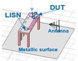

Simulation setup — Ansys HFSS software
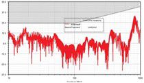
Simulated radiated noise vs. frequency
Electromagnetic near-field noise plot — Ansys SIwave results
Let’s Get Started
If you're facing engineering challenges, our team is here to assist. With a wealth of experience and a commitment to innovation, we invite you to reach out to us. Let's collaborate to turn your engineering obstacles into opportunities for growth and success. Contact us today to start the conversation.