-
-
Access Free Student Software
Ansys empowers the next generation of engineers
Students get free access to world-class simulation software.
-
Connect with Ansys Now!
Design your future
Connect with Ansys to explore how simulation can power your next breakthrough.
Free Trials
Products & Services
Learn
About
Back
Products & Services
Back
Learn
Ansys empowers the next generation of engineers
Students get free access to world-class simulation software.
Back
About
Design your future
Connect with Ansys to explore how simulation can power your next breakthrough.
Free Trials
ANSYS BLOG
September 14, 2022
Getting a Heads-up on the Road With Optical Simulation
Essentially, an automotive head-up or heads-up display (HUD), gives you exactly what the name suggests — a heads-up. The HUD is a transparent display in an automobile that projects information above the dashboard, usually visible on the windshield. By positioning the display at this level, drivers can keep their eyes on the road — and their heads up — while reviewing data such as road and driving conditions, including speed limits, traffic, fuel levels, and more.
According to market research and consumer studies conducted by Mordor Intelligence, the automotive HUD market recorded about $1.27 billion in 2021 and is expected to reach over $3.72 billion by 2027, with a compound annual growth rate (CAGR) of more than 24% between 2022-2027.
With anticipated growth like this, car manufacturers are turning to simulation now more than ever to accelerate and optimize HUD development.
Engineers and designers benefit greatly from optical simulation tools such as Ansys Zemax OpticStudio, Ansys Zemax OpticsBuilder, and Ansys Speos to simulate a system’s optical performance and evaluate the final illumination effect based on human vision — but that’s not all they are capable of doing.
Simply put, by using the software together, designers can view the creation process of their optical HUD designs in a whole new light.
Look Through Your Future Design
Virtual prototyping helps you qualify and evaluate countless windshield design options early in your development process, which saves significantly on material costs and time.
In optical design, the HUD is typically comprised of two mirrors. One mirror can be flat while one is freeform or both can be freeform. However, an additional mirror can also be needed. Though mirrors do not add any chromatic aberrations in an imaging system (i.e., deviation of light rays through a lens causing images of objects to be blurred), any freeform mirror must still be optimized. One of the main challenges of mirror placement is maximizing the available space within the dashboard design. As a solution, the optomechanical packaging capabilities of OpticStudio and OpticsBuilder are key to balancing both the mechanical constraints and the optical performances targets.
Conveniently, the design selection area of OpticStudio includes a template with a freeform model of the whole windshield (described as an extended polynomial surface), but you can also model a select area that will be located near the HUD by using the footprint diagram tool. This tool displays the footprint of the beam superimposed on the windshield surface.
To position all the elements in your model and determine the best surface placement, OpticStudio provides tools such as the coordinate break return and chief ray solve to simplify complex coordinate calculations.
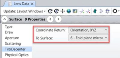
Figure 1. In Ansys OpticStudio, a coordinate break surface can be defined with a coordinate return under surface properties by selecting Tilt/Decenter.
For example, a coordinate break surface can easily be defined with a coordinate return under surface properties by selecting Tilt/Decenter. Eliminating manual input, OpticStudio will then calculate the parameters of that coordinate break surface so any local coordinates will be identical to the local coordinates of the previous surface, saving significantly on time.
Building upon this, the chief ray solve tool calculates tilts and decenters of a coordinate break surface so it is positioned both perpendicular to and centered on the chief ray.
Before exiting the Lens Data section, you can also use the Lens Data Editor tool to access and browse the CDGM materials catalog. The CDGM Glass Company Ltd., located in China, is the largest producer of optical glass in the world.
OpticStudio also enables you to visualize and predict initial optical design performance through full-field aberration analysis, which calculates the polynomials of the wavefront — the set of all points that have the same phase — and displays the coefficients across the full field of view.
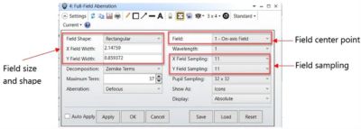
Figure 2. In OpticStudio, you can visualize initial performance with full-field abberation analysis, which calculates polynomnials and displays the coefficients across the full field of view. The full field of view is defined by the automated calculations, shown in the red boxes above.
Once your model is ready, you can continue to optimize within OpticStudio, check optomechanical integration with OpticsBuilder, or jump over to Speos to enhance your design.
The user-friendly, intuitive set of features within Speos are presented in a 3D platform, which helps you create designs from scratch or optimize current designs by seamlessly integrating layout and shapes directly into any computer-aided design (CAD) environment for realistic visualization. Similarly, its HUD design and analysis feature is compatible with computer numerical control (CNC) machining. This means you can export Speos-generated optical surfaces as polynomial coefficients and transmit this information to a CNC machine to produce enhanced optical surfaces, which streamlines data transfers between part suppliers.
Additionally, OpticsBuilder automatically converts and builds the OpticStudio system into CAD. This enables the mechanical engineer to check and quantify the impact of the packaging in CAD and ensure it is within the range defined by the OpticStudio user. As another option, the mechanical engineer can also edit the positions of the optical elements to ensure they will fit into the limited available space and send the full system back into OpticStudio for a review by the optical engineer.
The HUD design and analysis feature in Speos also enables you to study the technical feasibility of your HUD according to windshield shape and packaging constraints. This capability lets you design imaging systems quickly and easily based on individual automobile parameters. Coupled with this, Speos offers more than a dozen other capabilities and features that equip you with the optical tools you need to design the sharpest, most accurate HUD possible.
Built-in automatic tools help design the optical system and improve the perceived quality of the image by optimizing layout and shapes, generating a rotation axis, calculating angles for multiple drivers’ head levels, and automatically displaying the required optical volume. Optical volume is the space needed for the driver to view a full image from within the eye box.
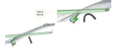
Figure 3. This diagram illustrates optical volume, the space allotted for the driver to view a full image from within the eye box.
The software also lets you qualify the image quality and compare several technical options, validating optical and vision performance. For example, you can check the compliance against your own acceptance criteria and create a complete simulation of the driver’s perception.
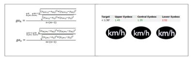
Figure 4. Traditional manual methods to check a design against requirements using complex optical metrics definitions (left). A head-up display (HUD) report in Ansys Speos, which uses customized plugins to easily check original equipment manufacturer (OEM) requirements as pass or fail tests (right).
Another core functionality within Speos is its extensive optical library, which includes more than 4,200 samples of lights and materials. With the aid of this online database, you can create physically correct simulations by selecting the best source, material, sensor, and standard models for any project.
Still, the most advantageous feature in Speos is likely its human vision component. Through this capability, you can determine visual aspects, reflection, visibility, and information regarding legibility according to the individual human observer. You can simulate visual predictions based on physiological human vision modeling; improve visual perceived quality by optimizing colors, contrasts, harmony, light uniformity with a homogenous lit appearance, and intensity; and consider ambient lighting conditions, including day and night vision.
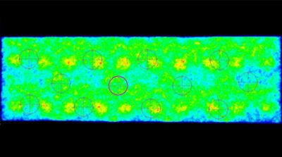
Figure 5. Speos HUD luminance (cd/m²) simulation taking polarization into account and a pass-or-fail customized test for the Society of Automotive Engineers (SAE) J1757-2 standard, which specifies distance requirements for HUD evaluation.
Setting Your Sights
By using OpticStudio, OpticsBuilder, and Speos, you can perform powerful light analyses and illumination evaluation across the electromagnetic spectrum while creating high-fidelity designs based on human vision capabilities. In addition, with the ability to determine both mechanical and optical design parameters simultaneously, you can shorten development time by increasing productivity.
Further, with GPU compute, Speos delivers significant improvements to simulation performance without compromising accuracy. Benchmarks indicate a 140x to 260x speedup on average.
Request a free trial of Ansys Zemax OpticStudio or Ansys Speos today!