-
-
Access Free Student Software
Ansys empowers the next generation of engineers
Students get free access to world-class simulation software.
-
Connect with Ansys Now!
Design your future
Connect with Ansys to explore how simulation can power your next breakthrough.
Free Trials
Products & Services
Learn
About
Back
Products & Services
Back
Learn
Ansys empowers the next generation of engineers
Students get free access to world-class simulation software.
Back
About
Design your future
Connect with Ansys to explore how simulation can power your next breakthrough.
Free Trials
ANSYS BLOG
March 7, 2023
4 Steps to Precisely Analyze Stray Light for Cameras Using Zemax Import and Speos Analytics
More than ever, a primary challenge in the design of many optical products is achieving the clearest possible image, whether it's for a space-based telescope, a nanoscale camera, or the head-up display (HUD) in a car. This image quality is measured by resolution and contrast. Stray light can lead to unwanted bright spots, which reduces image contrast and a system’s dynamic range.
In the case of smartphone cameras, stray light is a common culprit for blurring and discoloring images. Because the cameras can be used in virtually any environment, their design must account for stray light in a variety of existing lighting conditions, such as dimly lit rooms, outdoor playgrounds on a sunny day, and busy nighttime roadways full of streetlights, moving vehicles' headlamps, and lighted signs.
With the ongoing market imperatives to make smartphone cameras smaller and more lightweight, optical teams need tools and protocols that will help them identify and remediate stray light in their designs to preserve superior image quality.
What is Stray Light and how do you fix it?
You design optical systems for the desired path you want light to follow through the optics en route to a sensor. Stray light is the unwanted scattered or spectral light that also arrives at the sensor, which compromises the image quality of optical designs by distorting and washing out the image — effectively reducing the sensor's overall dynamic range.
To solve this problem, you seek ways to identify extraneous critical light source positions, which can be inside or outside the camera’s field of view. You then design methods for remediating the stray light's influence, typically by reconfiguring the lenses in the camera or swapping in new materials that have different optical properties.
Ansys Speos and Ansys Zemax OpticStudio include powerful capabilities for performing stray light analysis to help reduce or eliminate stray light at an optical system's sensor. The two products are designed to interoperate for this purpose with efficiency and ease.
- With OpticStudio, you can run high-precision analysis and design and optimize optical systems, accounting for the impact of thin film coatings and optomechanical geometries on optical performance of the “idealized” system.
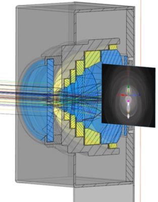
Figure 1. Stray light analysis in optics is the practice of accounting for undesired paths of light and preventing them from striking an optical system's sensor.
- Using the Zemax Import tool, you can automatically pull the OpticStudio data into Speos, apply relevant parameters to the data, and continue to refine the design with respect to stray light influence via additional simulation-based analytics.
Let's take a high-level look at how this interoperability between the two software packages typically works.
Easy 4-Step Workflow to Analyzing Stray Light in Smartphone Camera Lenses
1. Create the lens design and import it into Speos.
Using OpticStudio simulation and stray light tools, you can build and refine the lens system for your optical design. OpticStudio saves the lens parameter data in a Zemax OpticStudio (ZOS) file format, which can be automatically uploaded in Speos using Zemax Import. This automation provides greater efficiency and accuracy over manual data transfer, which takes more time and introduces potential human error.
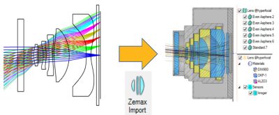
Figure 2. Zemax Import automates data transfer between a lens system design in OpticStudio (left) and a parameterized native view of each lens in Speos (right).
In Speos, the Projection Lens feature recreates each lens based on a native computer-aided design (CAD) geometry with access to all lens parameters in the data file. Speos converts all data into its native format and applies optical properties to the lenses.
2. Detect the light conditions that might cause stray light.
You can use the Light Expert (LXP) feature in Speos to identify and study the stray light conditions that will impact your design, including light sources within the camera's field of view (FOV) and potential light leakage in your system's mechanical housing from beyond the FOV.
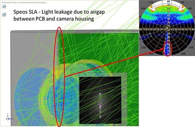
Figure 3. Light leakage due to airgaps between the printed circuit board (PCB) and camera housing.
Using backward ray tracing — sending rays from the imager through the system (created in Step 1) to the scene — enables you to detect all possible critical light source positions within one simulation. Speos’ powerful LXP capabilities enable you to display these critical ray paths.
3. (Optional) Conduct additional simulations based on known likely sources.
Beyond the analysis yielded by the parameterized data passed from the optical design, you can conduct further simulations based on other conditions likely to exist for the system user. For example, Figure 4 shows the simulation of a full-system stray light analysis. Once you have identified and mitigated any critical light sources outside of the camera’s FOV, you can define sun positions within the FOV using an accurate spectral sunlight to simulate the stray light patterns on the imager.
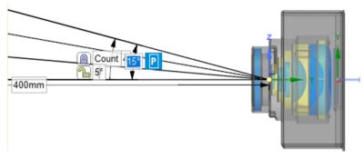
Figure 4. Full-system stray light simulation for four different sun positions, from 0 deg to 15 deg, within the camera FOV of a proposed optical design.
Note: For these simulations, it's recommended that you have access to additional processing power to run the necessary calculations. Speos is designed to operate optimally in high-performance computing (HPC) environments, but in the event you don't have HPC, recent Speos developments have also optimized analytics performance using certain graphics processing units (GPUs). To learn more about Speos GPU-Compute, watch this webinar.
4. Analyze the Stray Light Path Sequences and Apply Mitigations
Using the analysis from the LXP simulation, along with the Speos Sequence Detection viewer, you can identify the most critical ray path sequences and object interactions that yield stray light in your design. The Sequence Detection tool in Speos contains information about all detected ray path sequences and object interactions sorted by energy contribution. You can then mitigate the risk of these stray light cases and apply remediation measures by making further changes to the design, such as by applying a nonreflective coating or changing other material properties.
To learn more details about these four steps and follow an example demonstration based on the "four sun positions" scenario described in the previous step, read our App Gallery article.
For more information about Ansys Speos or Ansys Zemax OpticStudio, visit the Ansys Optics page.