-
-
Access Free Student Software
Ansys empowers the next generation of engineers
Students get free access to world-class simulation software.
-
Connect with Ansys Now!
Design your future
Connect with Ansys to explore how simulation can power your next breakthrough.
Countries & Regions
Free Trials
Products & Services
Learn
About
Back
Products & Services
Back
Learn
Ansys empowers the next generation of engineers
Students get free access to world-class simulation software.
Back
About
Design your future
Connect with Ansys to explore how simulation can power your next breakthrough.
Free Trials
ANSYS BLOG
August 30, 2021
3 Reasons Why You Should Use Reliability Physics Analysis Over Mean Time Between Failure
When determining product reliability and potential failure risks of an electronic assembly, there are two types of reliability analyses that engineers often use: a handbook-based mean time between failure (MTBF) analysis and a simulation-based reliability physics analysis (RPA).
There are a number of limitations that arise when engineers rely solely on the handbook-based methods for reliability prediction. In this blog, we will discuss the potential consequences of using only handbook MTBFs and the advantages of incorporating simulation for product reliability analysis.
What is MTBF?
MTBF stands for mean time between failure and predicts elapsed time between inherent failures of a mechanical or electronic system during normal system operations. MTBF uses an empirical failure rate calculation based on historical component data. This data is compiled independently in different handbooks, such as the Telcordia SR-332 and the MIL-HDBK-217.
There are a number of limitations that arise when engineers rely only on the handbook-based MTBF method for reliability testing:
1. Over- and Under-predicting Product Failure
One limitation of the handbook-based MTBF method is that it assumes that failures are random in nature and occur at a constant rate once the failure rate calculation is generated. However, assuming that failures are random and occur at a constant rate is not always accurate. Studies have shown that the failure rates generated in these handbooks can vary widely, both from handbook to handbook — between MIL handbook and Telcordia — and from handbook to actual field failure data. What is worse is they can vary in both directions, both over- and under- predicting failures.

Table 1: Generic final output of a handbook MTBF analysis
2. MTBF Doesn’t Account for all Design Decisions
Potentially the biggest limitation of relying on an MTBF analysis is that it does not directly account for many global assembly effects. The initial inputs for the analysis include component information that can be found on the average bill of materials (BOM), component data sheets, and generic operating environments. However, more detailed inputs cannot be entered as the design matures, such as detailed housing geometry, board layout, fixturing, and more, that would enable engineers to evaluate reliability as they design the board. This is extremely limiting as the MTBF analysis does not consider critical design features that could potentially have significant impact on product failure – such as the proximity of stress concentrating mount points to sensitive components or the effects of an improperly chosen housing material on mechanical reliability.
3. Constrained Environmental Inputs and Load Applications
The MIL and Telcordia handbooks have defined strict qualitative environments that the electronic assemblies must be assigned to before reliability testing. These environments are defined by the Telcordia Standard and include ground-fixed environment, ground mobile, airborne environments, etc. Each of these environments corresponds to a failure rate modifying Pi factor that determines the overall failure rate of each electronic part. As environmental severity increases, the Pi factor increases and the failure rates of the components increase as well.

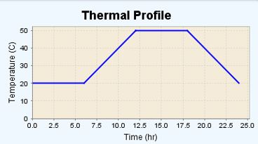
Table 2: MTBF empirically accounts for steady-state ambient temperature with a temperature factor and assumes failure rate increases with increasing temperature (an assumption that is not necessarily true). An MTBF may incportorate different operating temperatures of a product and the time spent at those temperatures, but it usually would not directly account for a thermal cycling profile such as this one. Source: Ansys
Unfortunately, there is no opportunity to apply specific loading conditions to an assembly using this method. Specific shock or vibration profiles or detailed thermal characterization of an operating environment is difficult, if not impossible, to include in a handbook MTBF analysis. Engineers will typically have to choose the handbook-defined environment that fits their use-case the best. This is an opportunity for error as the handbook environments may not adequately cover every specific, complex environment.
The Benefits of a Simulation-Based Reliability Physics Analysis (RPA) for Reliability Testing
RPA is defined as an engineering product development methodology that applies failure mechanisms models and knowledge developed by physics of failure (PoF) to produce failure-free products and systems. When combined with simulation, RPA can provide engineers with actionable information regarding product failure risks that are often much more accurate and detailed than handbook-based MTBF numbers alone.
Learn more about how Ansys Sherlock implements reliability physics analysis (RPA).
The top three benefits of RPA for reliability testing are:
1. Robust and Actionable Data
The reliability physics methodology is more concerned with the cause and effect of physical processes of the assembly, whereas handbook MTBF methods are more concerned with aggregating data into a single value for comparative purposes. RPA digs deeper into why certain parts fail under specific conditions, providing engineers with valuable and actionable insight that can help inform future iterations of the product design.

Table 3: Ansys Sherlock incorporates geometries to determine how component layout and board dimensions affect potential failure modes. Source: Ansys
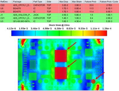
In addition, RPA provides more actionable data because it looks at specific geometries and environmental conditions when evaluating reliability. Without a simulation-based RPA, design engineers may not discover potential design issues until they prototype and physically test the boards. For example, by conducting an FEA simulation of a mechanical shock event and analyzing the resulting board strains with reliability physics, high-risk components can be specifically identified and mitigation techniques like adjusting mount points or underfilling components can be suggested.
The basic philosophy of RPA is to help engineers better understand the how and why of potential device failures so they can better prevent these risks, as opposed to the MTBF method, which simply says: This device fails at this rate.
2. Detailed Model Inputs and Load Applications
One of the limitations of MTBF analysis is the constraining criteria for model inputs and load applications. This is where the benefits of simulation-based RPA truly come into play. With simulation, engineers can build a three-dimensional model of the product and include important parameters like components’ shape and weight, board mounting conditions, and thickness. Additionally, it provides engineers the option to level up the design process to include effects from housings or other support structures, or go down a level and look at individual components and how internal features – like die attachment structures or lead frame shape – are affecting reliability behavior.

Table 4: Example of an RPA result set for a printed circuit board assembly (PCBA), showing shock strains calculated with simulation and resulting reliability predictions. Source: Ansys
The inclusion of such features in the analysis allows engineers to capture effects that can potentially influence failure behavior, like excessive strain fields due to under- or over-constrained assemblies and the mode shapes and natural frequencies in the system.
3. RPA Enables Multiple Iterations
A final important benefit of RPA simulation is that it enables engineers to constantly re-quantify reliability throughout the design process because of its iterative nature. Not only does RPA simulation capture geometries and specific use environments that can directly affect assembly reliability, but it can also rapidly iterate design changes like changing mount points, different environments, or component staking. This analysis then allows for optimizing such changes to determine how they will affect product failure risks and conclude which changes would most benefit the overall product design. This is really what makes reliability physics simulation an extremely powerful tool when compared to MTBF analyses alone.
