Synopsys and Ansys power the future of innovation—connecting silicon to systems.
ANSYS BLOG
April 21, 2016
Easy Simulation for Fatigue Analysis in Ansys AIM
In a wide range of structural applications, fatigue is common failure mechanism due to cyclic loading. Constant amplitude fatigue analysis is most commonly used to make a simple and quick estimate of fatigue performance or durability in absence of full time history based loading. With the release of Ansys 17.0, we are excited to introduce fatigue analysis in Ansys AIM for constant amplitude loading with support for both high cycle(stress life) and low cycle fatigue(strain life).
Ease of use with guided templates
Choice of fatigue methodology viz. high cycle(stress life) or low cycle(strain life) is critical part of fatigue analysis and is well articulated in earlier Ansys blog from Daniel Shaw. Both of these methods are supported in AIM with guided template where we can include fatigue analysis as part of “Structural template”. Common materials in AIM include fatigue properties and allow visualization of S-N curve or E-N curve.
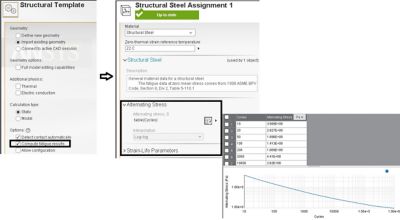
Showing structural template in AIM, also showing structural steal with S-N curve.
When fatigue material properties are not available, AIM makes it easy to run a fatigue computation based on a single input of fatigue strength using options in fatigue settings. Through fatigue settings, you also have the flexibility to define various constant amplitude loading types, various mean stress correction theories, multiaxial corrections with choice of stress components and units for fatigue life. You can review all fatigue results such as life, damage, safety factor, biaxiality indication and equivalent alternating stress.
It is also worth pointing out that fatigue results are available for all intermediate results sets in a nonlinear analysis, similar to other structural results. In this case, however the fatigue damage is non accumulative.
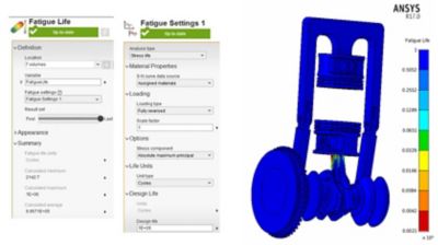
Visualizing fatigue life in a two piston model in a quasi-static analysis subjected to high pressure on its pistons and inertia load applied to the crankshaft via angular velocity.
The following example showcases how a fatigue-simulation driven iterative design of a ball bearing is carried out using Ansys AIM and Ansys SpaceClaim.
Fatigue driven Aircraft ball bearing design
Ball bearings are used in many applications that involve moving parts. This includes high speed applications such as aircraft's main bearings, jet engine shafts to low speeds applications such as gear boxes in cars or machine tool spindles. In these applications, repeated stresses are introduced to small volume of material which result in rolling fatigue failures. Rolling ball bearings are usually the weakest components that influence the remaining product life.
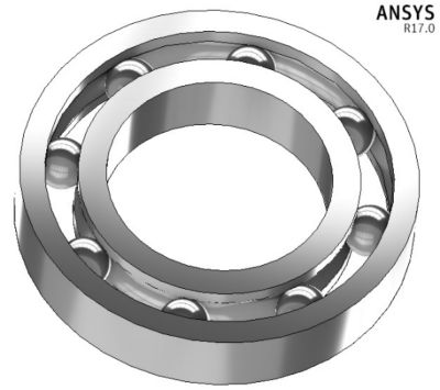
In the following ball bearing example, we study the fatigue characteristics under regular operating conditions of rotating ball bearing at a speed of 2865 rpm (300 rads/sec) and also carrying the dead weight of the rotor and engine (4KN, not modelled) connected to its inner rim. Further we look into iterative design to make sure the fatigue life and safety factor is within manufacturer's recommendations. The ball bearing is made of structural steel and consists 8 rolling elements as shown above. The ball bearing is modeled with nonlinear frictional contact using static analysis. Dynamic effects are achieved using inertia load with angular velocity applied to the inner rim.
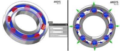
Showing contacts between the rolling elements with inner and outer raceways. Also visualizing free degrees of freedom of radially oriented rolling elements modeled with joints.
It is important to point out usually ball bearing use a retainer (not modeled) to keep the motion of rolling elements constrained within the inner and outer grooves. Joints are used in this model to achieve this purpose. After setting up the contacts, boundary conditions, a few mesh controls and appropriate solver controls, we solve the model and examine the results.
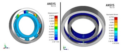
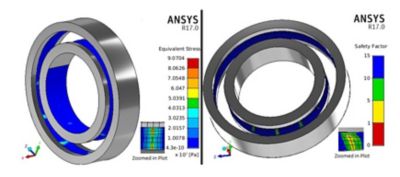
Showing deformation in y direction and equivalent stress of the ball bearing.
Peak equivalent von Mises stress is 127 MPa, and is found on the outer rim under the contact area near the rolling element radially downwards in negative y-axis. Its shape is an ellipse as expected from a Hertzian contact model. The bigger contact displacement is -0.16 mm, mainly concentrated on the lower part of inner ring. We can also review contact results such as changing status of rolling elements, sliding distance and contact frictional stress among the inner and outer ring and balls.
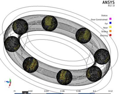
Showing all contact status results of rolling elements with groove faces at end of simulation.
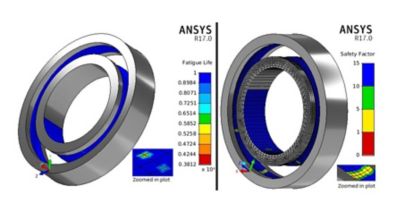
Showing fatigue life and safety factor in stress life fatigue analysis using zero based loading.
Reviewing fatigue life reveals minimum life to be 381k cycles and minimum factor of safety being 0.84(<1). This life and safety factor is below manufacturer’s recommendations, requiring bearing design changes.
Bearing Design
Assuming the rotor speed and weight of the machinery cannot be changed, we look into other parameters to increase ball bearing’s stiffness. One way to accomplish this would be to add more rolling elements. Ansys SpaceClaim easily allows you to add them with just a few simple clicks using the “Pattern” feature.
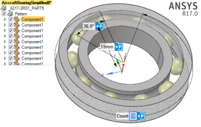
Showing editing the ball bearing geometry in Ansys SpaceClaim to add more rolling elements.
Iterating the simulation driven design to 8,10 and 12 balls reduces the maximum equivalent stress to 90 MPa (25% reduction). It also increases the minimum fatigue life greater than 1 million cycles and factor of safety to 2.0(>1.5, 100% more) well within a comfortable zone.
It might be interesting to study the impact on bearing life by changes of other geometric parameters such as groove diameter or the rolling element diameter.
Interested in Learning More?
AIM makes it easy to include fatigue analysis as part of linear or nonlinear structural analysis, helping your design process and product development costs both in time and money. Get an Introduction to Ansys AIM.