-
-
学生向け無料ソフトウェアにアクセス
Ansysは次世代の技術者を支援します
学生は、世界クラスのシミュレーションソフトウェアに無料でアクセスできます。
-
今すぐAnsysに接続!
未来をデザインする
Ansysに接続して、シミュレーションが次のブレークスルーにどのように貢献できるかを確認してください。
無料トライアル
製品およびサービス
リソースとトレーニング
当社について
Back
製品およびサービス
ANSYS BLOG
September 19, 2023
LC Filter Design with Ansys HFSS and Modelithics
Designing bandpass filters using lumped components is a challenging aspect of 5G system design. The frequency spectrum supported by 5G and the need to eliminate radio frequency (RF) noise while simultaneously maximizing channel availability presents plenty of headache-inducing problems to even experienced RF filter circuit developers.
The high frequencies and demanding system requirements of 5G, however, also push engineers to include physical factors inherent in the system environment, further complicating filter design efforts. Equivalent circuit models for RLC networks fail to account for electromagnetic problems such as coupling between components or their coupling to the printed circuit board (PCB), itself a dynamic source of potential signal integrity problems. PCBs also pack components as tightly as possible for cost and form factor reasons, with the resulting proximity of elements aggravating the potential for electromagnetic hazards.
There are further electromagnetic factors with which RF engineers contend in filter design for high-performance systems. The materials from which passive components are made have a notable impact on their electromagnetic characteristics. Even the 3D geometry of the lumped filter and its individual components is important.
Successfully dealing with this set of obstacles requires an appropriately sophisticated combination of data, models, and tools. The data and models are provided in this case by the Modelithics COMPLETE+3D component library, and the tool of choice is Ansys HFSS.
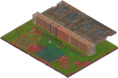
Ansys HFSS 3D layout
The Modelithics COMPLETE+3D Library is a collection of models for components from a wide range of vendors. Amongst the elements in the library are Microwave Global Models, which are equivalent circuit models for capacitors, inductors, and resistors that include parameters based on lab measurements. These models scale with respect to part values, substrates, and solder pad dimensions. Microwave Global Models capture substrate-dependent parasitic behavior and offer advanced pad features for electromagnetic (EM)/circuit co-simulations. Because a single Microwave Global Model can cover a full range of part values for a given part series, these models are ideal for scenarios that require tuning or optimization.
There is also a collection of encrypted 3D EM geometry models for discrete components as well as more complex objects such as filters and IC packages. An additional set of models in the COMPLETE+3D library is the 3D “brick” models for multilayer ceramic capacitors. These are simplified models that approximate a multilayer ceramic capacitor’s (MLCC’s) physical geometry. Three-dimensional brick models are intended to be used in hybrid 3D co-simulations that combine the 3D brick model with the Microwave Global Model for the given capacitor to allow for a complete 3D EM simulation.
The models and their physical parameters can be used together and lend themselves well to full-wave electromagnetic simulations created to reveal signal integrity problems such as coupling. That simulation is performed using HFSS and its 3D Component and 3D Layout functions.
Simulating the electromagnetic behavior of mmWave systems in 3D has become a critical step in RF design. Packing high-speed, high-bandwidth components into minimal form factors creates electromagnetic interactions that conventional circuit simulations and 2D electromagnetic modeling simply cannot capture properly. False signals, data loss, and performance reduction are some of the problems that can result from 3D coupling.
The Modelithics COMPLETE+3D library is available as a pull-down menu selection in HFSS. The components already incorporate boundary conditions, material properties, and excitations, simplifying their usage in simulation. Adding selected components as desired to a PCB target is a straightforward operation through a pull-down menu. With the components already installed in the target PCB, an HFSS user can simulate them together as a system, with the physical attributes of the component automatically included.
HFSS also offers a 3D layout capability that can simulate PCBs and their components together and include the vertical dimension of the board with its individual layers. HFSS 3D Layout supports highly complex board, package, and connector geometries. Much of the layout setup is automated, as HFSS 3D Layout accounts for pin locations (including power and ground) and places components automatically after importing the CAD file. Port excitations are also created automatically. Once a designer selects frequency sweep parameters, the simulation is ready to launch, with a setup time of just a few minutes.
Modelithics applications engineer Chris DeMartino describes the COMPLETE+3D library in greater depth and shows how it can be used in conjunction with HFSS to simulate LC filters in RF designs using several examples in this webinar: Designing Densely Packed LC Filters With Ansys HFSS and Modelithics.