Synopsys and Ansys power the future of innovation—connecting silicon to systems.
主題詳細資料
什麼是雷諾數 (Reynolds Number)?
流動流體的雷諾數 (Re) 是一個無因次量,工程師有時會用它來協助預測在不同情況下的流動型態。它代表慣性力與黏性力的比率。此比率代表液體或氣體的移動是遵循平均流線 (層流流動),或平均流線周圍有不穩定的波動 (紊流流動)。
當對速度變化的阻力 (慣性力) 超過了對流體中不同層與任何固體邊界之間相對運動的力 (稱為黏性力) 時,紊流流動中流體的混亂行為就會發生。
雷諾數較高表示流動由慣性力主導,且會產生紊流流動。反之,雷諾數較低則表示流動由黏性力主導,且呈現示平滑或片狀的層流流動。
從實務角度來看,雷諾數是流體力學中的基本無因次量,可有效減少所需的變數數量,並在可擴充系統中實現物理現象的有意義關聯。工程師和科學家可以使用雷諾數的計算值來預測流場是否將從層流轉變為紊流流動,以及發生轉變的流場位置,以決定在模擬流動類型時套用哪些方程式,並比較不同應用或尺度的流場。
無論是設計機翼形狀,還是為工業系統中流體的複雜行為建模,流體動力學家都可以從計算所研究之流動情況的雷諾數著手。
雷諾數的歷史
George Stokes 在 1851 年引入了根據慣性力和黏性力比率來判斷可能發生紊流流動特性的概念,這是在開發 Navier-Stokes 方程式的研究中引入的。然而,直到 Osborne Reynolds 開始研究紊流流動在管道中的發展時,這個概念才真正獲得具體且實際的應用。他在 1883 年發表了一篇論文,描述「決定水運動為直接或彎曲,以及平行通道中的阻力定律之情況的實驗調查。」
這些實驗將一道染劑注入裝有水的透明玻璃管中央。Reynolds 使用控制閥來改變流動,當速度較低時,染料會集中在一起停留在中央。然而,當速度增加時,染料層會分解並擴散到水中。這篇論文將擴散開始的位置定義為轉換點。
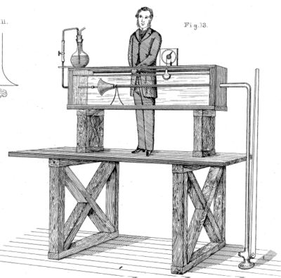
Osborne Reynolds 在 1883 年的論文中使用的測試裝置圖
在檢閱資料時,Reynolds 推導出可預測層流到紊流流動轉換的無因次參數,為流體密度、管道直徑、流動速度和流體黏度變化的函數。Reynolds 並未以自己的名字為這個無因次數命名。而在 1908 年,Arnold Sommerfeld 在一篇論文中使用該值,並以 Reynolds 的名字命名。
雷諾數方程式
基本雷諾數方程式是慣性力和黏性力的比率。工程師根據所需應用開發了數種不同形式。每種應用都有一個特性長度尺度,定義距離 (如直徑或長度),以及一個特性速度,以流速、質量流動或體積流動表示流速。
以下是用於雷諾數最常見的形式列表:
$$R_e = \frac{慣性力}{黏性力} $$
$$R_e (動態 \空間黏度) = \frac{\rho uD_h}{\mu} $$
$$R_e (運動學 \空間黏度) = \frac{uD_h}{\nu} = $$
$$ R_e (體積 \空間流速)= \frac{\rho QD_h}{\mu A} $$
$$ R_e (質量流速) = \frac{WD_h}{\mu A} $$
$$ R_e (翼弦長) = \frac{VL_c}{\nu}$$
$$ R_e (平 ~ 板) = \frac{Vx}{\nu}$$
其中 (使用 MKS 單位):
流體屬性
| ⍴ | 流體密度 (kg/m3) |
| 流體的動態黏度 (kg/mᐧs) | |
| $$ {\nu}$$ | 流體的運動學黏度 (m2/s) |
特性速度
| u | 流體的平均速度 (m/s) |
| Q | 流體的體積流速 (m3/s) |
| W | 流體的質量流速 (kg/s) |
| V | 機翼通過流體的速度 (m/s) |
特性長度尺度
| Dh | 管道、線管或導管的液壓直徑 (ms) |
| A | 管道的橫截面積 (m2) |
| Lc | 翼弦長 (m) |
| x | 從板前緣起的長度 (m) |
雷諾數在瞭解層流到紊流流動轉換中的角色
任何參與研究或使用流體動力學的人都想要瞭解其正在使用系統中的流動模式。有時他們想要層流流動,有時他們想要紊流流動。因此,瞭解流體運動在何種流動條件下會成為紊流至關重要。
對於直徑為特性長度的圓管內的流動,當 Re 小於 2,300 時為層流流動,而紊流流動會在 Re 大於 2,900 時發生。您可以在這裡看到,雷諾數較低表示黏性力能讓流動保持穩定且沿著流線。管路中這個較低的數值 ── 2,300 ── 稱為臨界雷諾數,因為它表示流動將從層流轉變為紊流的臨界點。
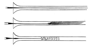
來自 Reynolds 原始論文的圖示顯示 (從上到下) 低速層流流動,較高速混合,以及電火花所呈現的渦流。
對於平板上的流動,特性長度是與平板上游 (或前導) 邊緣的距離。速度是邊界層外的自由流速度。根據此定義,流動在平板成為紊流的臨界雷諾數通常為 5 x 10⁵。
過去,流體動力學家會透過實驗判定每個應用在特定流體類型和幾何拓撲中,指出完整發生的紊流流動所使用的臨界雷諾數值。接著,他們會使用這些值來預測紊流會發生的位置,並進行變更,以誘發或阻止這類流動。如今,使用計算流體力學 (CFD) 的工程師有時會使用雷諾數來決定應該使用哪些紊流模型,以及應用它們的位置。
雷諾數的常見錯誤應用
雷諾數對環境高度敏感,並使用簡化的流動表示法。下表列出工程師在使用雷諾數時最常見的錯誤:
- 未使用正確的特性長度、特性速度或速度測量位置。
- 在正確 Re 應用實際差異顯著的複雜幾何上套用 Re 計算器。
- 忽略轉換區域,即流動開始轉換和完全成為紊流的 Re 範圍。
- 僅依靠雷諾數來描述流態特性,特別是在尺度縮放時。在超音速流動中進行縮放時,馬赫數扮演關鍵角色,或是當重力是驅動力時,福祿數變得重要。
- 在非牛頓黏性流體上使用雷諾數,其中黏度會隨剪率變化,例如在聚合物和血液中。
- 在流動中混合液體、氣體或固體的多相情況下,套用雷諾數。
- 忽略會變更臨界雷諾數值的外部因素,包括上游條件、表面粗糙度、流動擾動,以及溫度波動引起的密度變化。
雷諾數的其他應用
以雷諾數表示的內部力與黏性力比率還有其他應用方式,工程師可用來計算不同的值並推動設計。其中一些最常見的是:
- 邊界層厚度:邊界層厚度的公式 (使用根據與邊界距離 x 計算的雷諾數。
- 化學工程:化學工程師使用雷諾數來描述隨著紊流而變化的化學反應,特別是在邊界層很重要的情況下,或速度與慣性力的比率會影響反應速率的情況下。
- 阻力係數:阻力係數表示物體通過流體時所經歷的阻力,這是雷諾數的函數。空氣動力學和流體動力學工程的一大重點在於瞭解和管理系統的阻力係數。
- 流動分離:在流動分離中,造成流動偏離邊界的逆壓,會受到臨界層附近紊流的影響。對於高雷諾數,紊流流動中的能量會抵消推動分離的力。黏性與內部流動的比率 Re 也會控制流動保持與非平面表面的附著能力。
- 摩擦係數:當流體相對於物體流動時,因摩擦引起的能量損耗可透過摩擦係數量化,摩擦係數與 Re 直接相關。在低雷諾數值的層流流動中,摩擦係數僅取決於 Re。在高雷諾數值形成紊流時,表面的粗糙度也會扮演重要角色。
- 熱傳遞:進行熱傳遞研究的機械工程師不僅需要知道流動是紊流還是層流。對流熱傳遞中的關鍵值是紐塞爾數 (Nu),其公式中使用了 Re。
- 尺度縮放:Reynolds 進行的實驗中最有用的發現之一,是工程師如何使用動態相似度來放大或縮小產品尺寸,以進行風洞測試。如果特性長度改變,則需要不同的流速才能維持類似的 Re 值。
藉由 Ansys 縮短開發時間
工程師在各種產業中使用 Ansys CFD 軟體,模擬在複雜幾何形態中的流體流動與熱傳遞。從概念設計、最佳化到最後階段測試,Ansys CFD 解決方案提供簡化工作流程、進階物理建模功能,以及可信賴的準確結果,幫助您做出設計決策。
深入瞭解 Ansys Fluent 流體模擬軟體,領先業界,並以其先進的物理建模功能和準確度聞名的流體模擬軟體。
您也可以查看Ansys CFX 計算流體力學軟體,領先業界的渦輪機械應用 CFD 軟體,其提供準確且有效率的方式來模擬渦輪機械的複雜流動物理,例如壓縮機、渦輪機和泵。
相關資源
讓我們開始吧
如果您面臨工程挑戰,我們的團隊將隨時為您提供協助。憑藉豐富的經驗和對創新的承諾,我們邀請您與我們聯絡。讓我們共同合作,將您的工程障礙轉化為成長和成功的機會。立即與我們聯絡,開始對話。