Synopsys and Ansys power the future of innovation—connecting silicon to systems.
-
-
학생용 무료 소프트웨어에 액세스하기
차세대 엔지니어에게 힘을 실어주는 Ansys
학생들은 세계적 수준의 시뮬레이션 소프트웨어를 무료로 이용할 수 있습니다.
-
지금 바로 Ansys에 연결하십시오!
미래를 설계하기
시뮬레이션이 다음 혁신을 어떻게 지원할 수 있는지 알아보려면 Ansys와 연결하십시오.
무료 트라이얼
제품 및 서비스
학습하기
회사 정보
Back
제품 및 서비스
ANSYS ADVANTAGE MAGAZINE
January 2021
Use CFD to Improve Efficiency and Reduce Emissions
By Duraivelan Dakshinamoorthy Vice President Tailwater Technical Consulting LLC Houston, U.S.A.
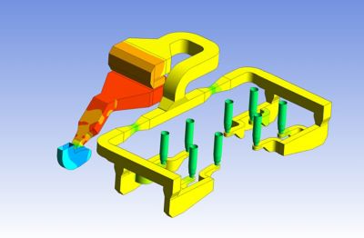
Figure 1: Contours of a combustion air pressure profile across a forced draft fan, air preheater, air plenum and burner
Energy efficiency is essential to convert crude oil and natural gas into fuels that provide energy to the entire world. Simulation enables the oil and gas industry to improve efficiency and reduce emissions of fired heaters.
Fired heaters are the energy workhorses of the oil and gas industry. In a fired heater, thermal energy is released by combustion of fuel (gas, oil or both) and is then transferred to process fluids via radiant and convection tubes. However, all the energy supplied by combustion is not transferred to the tubes; thus fired heaters are major consumers of energy within the oil and gas industry. Improving the efficiency of the heaters decreases energy consumption, thus reducing operating costs. In the current environment of low crude oil prices, a penny saved is a penny earned.
Fired heaters produce waste flue gas from the combustion process that is discharged to the atmosphere. Flue gas is primarily nitrogen (N2), carbon dioxide (CO2), water vapor (H2O) and oxygen (O2). In addition to this, flue gas may also contain small concentrations of pollutants (emissions) that include carbon monoxide (CO), nitrogen oxides (NOx ), sulphur oxides (SOx ), particulates and metals. Emissions are harmful to the environment, and efforts must be made to reduce the pollutants from the fired heaters and meet strict environmental regulations that limit emissions from fossil fuels.
To improve efficiency and reduce emissions, proper understanding of fired heater design is essential. Ansys Fluent is now used extensively by the oil and gas industry while designing fired heaters. Fluent allows engineers to visualize design details in the front-end engineering design (FEED)/detailed engineering stage of the project, where cost of change is minimal. The following cases give a glimpse of how Fluent is used in improving efficiency of the heater and reducing emissions.
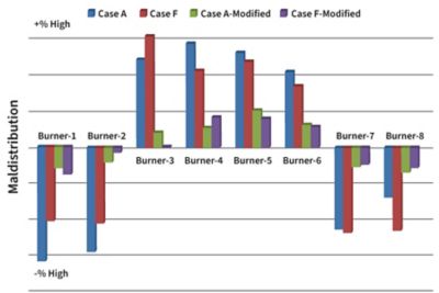
Figure 2: Maldistribution improvement for proposed modified design
Combustion Air Ducting Design to Control Excess Air
For complete combustion, air in excess of the stoichiometric amount is needed. Fired heaters are usually designed to receive 10% to 15% excess air. Too much excess air will reduce the efficiency of the heater and increase energy consumption. Engineers employ various means to deliver the proper amount of excess air to fired heaters. Natural draft heaters are most common. They are simple and reliable, as the air is drawn into the burners by the draft in the radiant section. Forced draft heaters require a forced draft (FD) fan to supply the air at the higher pressure. The fans provide better mixing so one can have multiple smaller burners. In some cases, forced draft heaters are equipped with air preheaters (APH) to improve the heater efficiency. Since air is supplied through a manifold and an air plenum, the design engineer must make sure air is supplied uniformly to all the burners.
Fluent is extensively used in investigating and eliminating maldistribution concerns during the design stage. Maldistribution, if undetected, would force the fired heater to operate with a higher rate excess air or a lower efficiency. Figure 1 shows one such combustion air ducting system. The system was modeled from the intake of the FD fan to the individual air plenums. The combustion air passes through the APH and the venturi flow meters along the way. Maldistribution was identified and eliminated using Fluent (see Figure 2).

Figure 3: Flame shapes for multiple cell, multiple burner heater and also Figure 4: Aqueous ammonia profile in flue gas from injection point
Combustion Flame Profile Modeling
Burner manufacturers are focused on finding different means to limit NOx from the burners, and computational fluid dynamics (CFD) has played a major role in developing and designing the next generation ultra-low NOx burners (ULNBs). In most cases, fuel/air staging methods are used in limiting NOx from combustion, which often leads to cooler but longer flames.
In a large furnace with multiple ULNBs, there is the possibility of flame-to-flame interaction and flame impingement on tubes. The flame length is often a critical burner parameter that is required for proper placement of burners and radiant tubes. The flue gas recirculation in the radiant box also affects the flame pattern.
When designing fired heaters with multiple ULNBs, Fluent is often used in modeling the combustion process in the radiant section. Figure 3 shows one such complex fired heater with four radiant sections (cells) with multiple burners. The flame patterns were identified and checked for interactions with neighboring burners. Radiant heat transfer was modeled and the resultant tube metal temperatures on the radiant tubes were predicted. Hotspots with higher radiant heat flux often pose coking concerns. Fluent identified this in the design, and changes were made to reduce the hotspots.
Designing SCR Systems to Reduce NOx Emissions
NOx emissions can be controlled by two methods: precombustion technologies (use of ULNB, flue gas recirculation, etc.) and post-combustion technologies. Selective catalytic reduction (SCR) is a post-combustion NOx reduction technology.
With SCR, aqueous ammonia (NH3 ) is injected into the flue gas using a carrier stream (air) through an injection grid (AIG). The injected ammonia mixes with the flue gas containing NOx in the flue gas duct. The mixed stream is then sent to the SCR unit, which contains a catalyst bed. Ammonia then reacts with the NOx in the catalyst bed to form nitrogen and water. This technology requires an effective injection system and an optimized duct design for better emission reduction. Mixing is usually challenging, because the amount of injected ammonia (ppm) is very small compared to the flue gas volume. Figure 5 shows an SCR unit with an upstream duct containing the AIG. Fluent is used in designing the injection grid and the upstream duct. The post-processing tools in Fluent allow engineers to understand how the injected ammonia mixes with the flue gas as it reaches the catalyst bed (see figure 4).
Properly designed heaters operate safely and efficiently with controlled emissions. Controlling excess air reduces fuel consumption and increases efficiency. Understanding flame patterns and resultant tube metal temperatures increase longevity of the heaters with minimized risk of unforeseen shutdowns. The SCR unit’s emission reduction efficiency increases with an effective injection grid and an optimized upstream duct design.
In all the cases discussed, Fluent has played a key role in the heater design and has added real engineering value.
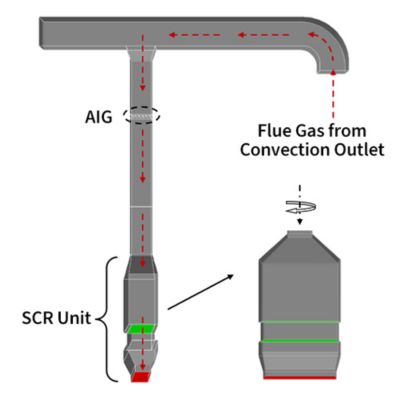
Figure 5: Selective catalytic reduction unit and ammonia injection grid design