-
-
Software gratuito per studenti
Ansys potenzia la nuova generazione di ingegneri
Gli studenti hanno accesso gratuito a software di simulazione di livello mondiale.
-
Connettiti subito con Ansys!
Progetta il tuo futuro
Connettiti a Ansys per scoprire come la simulazione può potenziare la tua prossima innovazione.
Paesi e regioni
Customer Center
Supporto
Partner Community
Contatta l'ufficio vendite
Per Stati Uniti e Canada
Accedi
Prove Gratuite
Prodotti & Servizi
Scopri
Chi Siamo
Back
Prodotti & Servizi
Back
Scopri
Ansys potenzia la nuova generazione di ingegneri
Gli studenti hanno accesso gratuito a software di simulazione di livello mondiale.
Back
Chi Siamo
Progetta il tuo futuro
Connettiti a Ansys per scoprire come la simulazione può potenziare la tua prossima innovazione.
Customer Center
Supporto
Partner Community
Contatta l'ufficio vendite
Per Stati Uniti e Canada
Accedi
Prove Gratuite
ANSYS BLOG
August 6, 2018
How to Efficiently Simulate a Gas Turbine Flameout
If you perform as many gas turbine combustion and flameout simulations as I do, then you must be praying for the day that quantum computing becomes a reality.
The fine meshes you could process with quantum computing power would make simulating turbine behavior a breeze
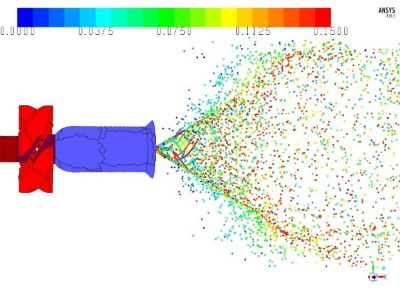
Gas turbine spray pattern colored by temperature using Ansys Fluent
Most CFD and combustion simulations rely on a limited, affordable mesh count. Engineers use coarser meshes than they would prefer for a fast turnaround with the available hardware resources.
However, simulation experts must ensure that these coarser meshes still achieve the desired accuracy. After all, these simulations are used to prevent accidents such as the engine flameouts of British Airways’ Flight 9 in June 1982 and Flight 38 in January 2008. Fortunately, mathematical models provide engineers with the accuracy they need on the mesh they can afford.
For example, finite rate effects — which result because combustion reactions do not occur instantly but take some time — are leading contributors to flameout in gas turbine engines. Simulating finite rate effects is challenging because you may need hundreds of scalars and fine-scale information to achieve accurate results.
Traditionally, this level of detail is beyond the affordable mesh resolution. However, Ansys Fluent users can use some cool tricks to simulate near-flame extinction using only a few scalars and a relatively coarser mesh than you might expect.
What Causes Turbine Flameout?
Flame extinction is caused by an excessive amount of heat transfer outside of the reaction chamber or a significant loss of chain-branching radicals. If either of these events happens, the heat loss is greater than the heat generated by the burning fuel, and the flame blows out — hence, the term “flameout.”
A simulation of turbine flameout using Ansys Fluent
Flameout conditions affect gas turbine engines at high cruise altitudes due to weather effects, fuel starvation, compressor stall or other mechanical failures.
Engineers use simulations to model flameout and near-flameout conditions. This empowers engineers to study, predict and limit flameouts by improving turbine designs.
How to Model Engine Flameout in Ansys Fluent
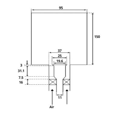
Cambridge bluff-body swirling burner
Engineers simulate flameout by accurately modeling the flame’s finite rate transient effects and its interaction with small turbulent eddies.
Flameout conditions occur under a low Damköhler number (Da). The Da number is defined as the ratio of the characteristic turbulence time scale and the characteristic chemical time scale.
Ansys Fluent can simulate swirling spray flames near extinction in a Cambridge bluff-body swirling burner. These simulations can then be used to compare a stable n-heptane flame (H1S1) and an n-heptane flame that is close to blowout (H1S2).
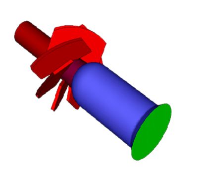
Six-vane swirler and bluff-body geometry
The simulation shows that the spray pattern is a 60-degree hollow cone (see figure below).
Spray pattern colored by temperature using Ansys Fluent
A stress blended eddy simulation (SBES) model is used to predict near-wall heat losses. This model accurately predicts the boundary layer conditions near the wall using a stress blending technique.
The SBES model resolves the near-wall boundary layer using a Reynolds-averaged Navier–Stokes shear-stress-transport (RANS SST-k-w) model. However, large eddy simulations (LES) are used to resolve the core turbulent flow.
The blending of the RANS and LES models allows for better near-wall heat transfer modeling and alleviates the need for a fine mesh near the wall. This makes flameout simulation more efficient.
A map showing where these two fluid dynamics models are used can be seen below.
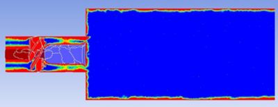
SBES blending function. Red indiciates RANS modeling and
blue indicates LES modeling.
A flamelet generated manifold (FGM) model in a Eulerian-Lagrangian framework is used to model the combustion of the system. The FGM models the complex evolution of the turbulent turbine environment with only a few scalars.
In other words, Fluent’s FGM can improve the efficiency of your simulation. The FGM details the chemistry as a function of the scalars, including:
- Mixture fraction mean.
- Mixture fraction variance.
- Progress variable mean.
- Progress variable variance.
- Mean enthalpy.
Finally, a conjugate heat transfer model is used to better predict the heat transfer between the flow and the bluff-body surface. The bluff-body wall temperature distribution is shown below.
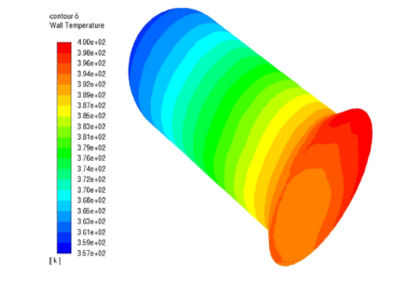
Bluff-body wall temperature distribution
How Flameout Simulations from Ansys Fluent Compare with Experiments
An instantaneous flame isosurface model shows how FGM can capture finite rate effects. The model (on the left) depicts an instantaneous snapshot of the flame surface which is colored by the OH mass fraction.
The isosurface model shows a few holes in the flame. These holes reflect local extinctions. However, the data also shows that these holes will eventually reignite. This study found that the data in this isosurface model compares well with experiments after the data has been averaged.
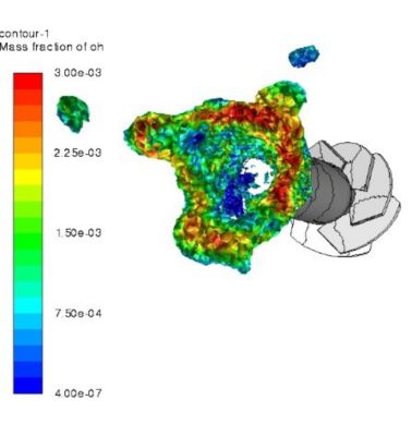
Instantaneous flame isosurface at T=1699-2200 K colored by OH mass fraction
Another flame surface can be seen below. This image is colored by the flame’s height above the bluff body.
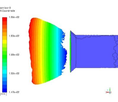
Mean flame brush visualized by an iso-clip of mean temperature
at a range of 1600-2000K
The simulation shows that the flame is lifted about 4-6 mm, in good agreement with experiments.
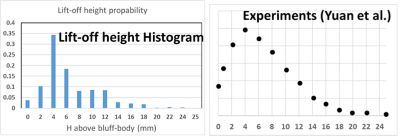
H1S1 flame liftoff height
In-addition, the simulated spray’s mean axial velocity shows good agreement with experimental measurements at different locations.
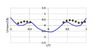
Mean spray axial velocity
In summary, the results shows the success of Ansys Fluent’s combustion tools to predict near-extinction characteristics.
If you want to learn more, watch our webinar “A New Paradigm in Turbulence Modeling for Aerodynamic Simulation”.