Synopsys and Ansys power the future of innovation—connecting silicon to systems.
-
-
Software gratuito per studenti
Ansys potenzia la nuova generazione di ingegneri
Gli studenti hanno accesso gratuito a software di simulazione di livello mondiale.
-
Connettiti subito con Ansys!
Progetta il tuo futuro
Connettiti a Ansys per scoprire come la simulazione può potenziare la tua prossima innovazione.
Customer Center
Supporto
Partner Community
Contatta l'ufficio vendite
Per Stati Uniti e Canada
Accedi
Prove Gratuite
Prodotti & Servizi
Scopri
Chi Siamo
Back
Prodotti & Servizi
Back
Scopri
Ansys potenzia la nuova generazione di ingegneri
Gli studenti hanno accesso gratuito a software di simulazione di livello mondiale.
Back
Chi Siamo
Progetta il tuo futuro
Connettiti a Ansys per scoprire come la simulazione può potenziare la tua prossima innovazione.
Customer Center
Supporto
Partner Community
Contatta l'ufficio vendite
Per Stati Uniti e Canada
Accedi
Prove Gratuite
ANSYS BLOG
April 14, 2023
Hairpin Winding – A Powerful Solution to Electric Machine Design
Hairpin winding is a relatively new technology that the automotive sector is increasingly interested in due to the growing affordability and effectiveness of manufacturing processes.
Compared to stranded windings, hairpins consist of rectangular conductors. It leads to a significant increase of the slot fill factor compared to traditional solutions: With stranded windings maximum values are around 0.45, hairpin technology goes up to 0.8.
The main drawback of this solution is the complex pattern design. When parallel paths are introduced, several rules need to be respected to get electromagnetically balanced hairpin patterns.
Many automotive original equipment manufacturers (OEMs) have migrated to this technology in the past few years. This winding solution offers many advantages to the design of electrical machines, which concerns electromagnetic sizing and cooling systems.
Electromagnetic Analysis
On the electromagnetic side, an improved copper slot fill factor reduces the space dedicated to slots and enables potentially higher torque and power density, along with a reduction in DC resistance. Assuming the same stator volume, a hairpin winding machine can be less saturated than its stranded winding counterpart, leading to lower iron losses. This is a key advantage, especially for drive cycles. Electric vehicle (EV) motors usually have a small number of series turns. This means a large number of strands in hand might be necessary, causing significant AC losses. A proper hairpin winding combination of layers and parallel paths can limit this loss.
Design Example and Comparison with a Stranded Winding Solution
A design comparison for a traction application motor is shown in Figure 1. The two machines are designed for the same voltage, current, and slot current density; they have been optimized for the same output performance. The hairpin winding motor enables for larger stator bore diameter with respect to the stranded winding solution, with the benefit of also having a shorter stack length and higher power density. The lower stator iron volume also represents an advantage in lowering iron losses.
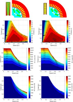
Figure 1. Efficiency and loss comparison between stranded and hairpin in a traction motor; geometry proportions are the same across both images.
Thanks to lower DC resistance, the hairpin machine clearly has higher efficiency in the base point and a significantly larger high-efficiency region. This is also due to lower AC losses in the hairpin winding machine. Stranded winding requires bundles of parallel wires in the slot to meet the voltage requirement and reach a good copper slot fill factor. These bundles, which represent the effective series turns, are particularly prone to high AC losses due to the circulating currents in the parallel wires. The chosen hairpin winding design with eight layers has significantly fewer AC loss, thanks also to a lower slot height.
Winding Design in Ansys Motor-CAD and Export to Ansys Maxwell
Ansys Motor-CAD automatically computes the hairpin winding wave pattern, dividing the scheme into different elementary windings. Each elementary winding is built to meet flux linkage balancing rules covering all the layers and all the slot per pole per phase and represent a potential parallel path. Different parallel paths combinations are possible by putting in series groups of elementary windings.
In Figure 2, the elementary windings are automatically generated, covering all the layers and slots per pole per phase. The coils matrix is defined in order to have the wave pattern (see Figure 3). In this case, eight parallel paths are possible, with the possibility to customize this number by selecting the elementary windings to put in series.
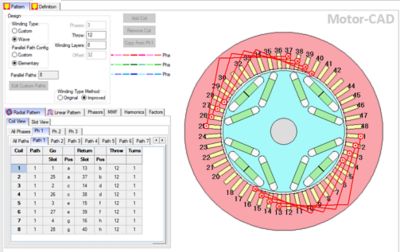
Figure 2. Automatic hairpin winding scheme with 48 slots, 4 poles, 8 layers, and 8 parallel paths.
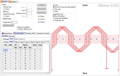
Figure 3. Each elementary winding is designed to respect flux linkage balancing rules and to exhibit the typical wave pattern of the end connections.
For a more detailed analysis of the circulating currents in the parallel paths, the Motor-CAD model can be exported to Ansys Maxwell, where the simulation with external circuit coupling can be carried out.
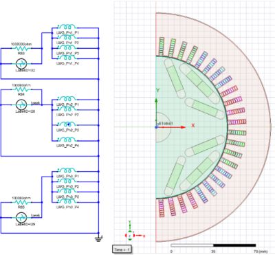
Figure 4. Ansys Motor-CAD model exported to Ansys Maxwell.
Drive Cycle Performance
Motor-CAD easily computes efficiency maps and performs duty cycles analyses, proposing the most common drive cycles as default options.
In Figure 5, the hairpin machine efficiency map is shown, with the US06 drive cycle’s working points highlighted. The average efficiency for this machine is 94.23%.
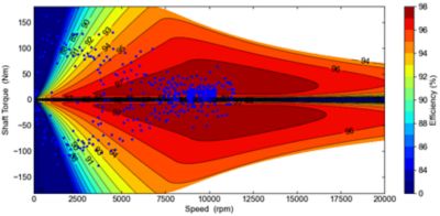
Figure 5. Hairpin winding machine efficiency map and US06 drive cycle's working points.
The same analysis is performed for the stranded winding motor and reported in Figure 6. Adopting this solution, the average efficiency drops to 93.77%.

Figure 6. Stranded winding machine efficiency map and US06 drive cycle's working points.
Coupled Thermal-Electromagnetic Analysis
The thermal model in Motor-CAD properly assigns DC+AC losses to each individual conductor. The resulting temperature profile is discrete, as shown in the finite element analysis (FEA) simulation reported in Figure 7. The same concept is also adopted for the thermal network.

Figure 7. Thermal model for hairpin windings.
The thermal model is particularly useful to evaluate a machine’s variable speed performance in continuous operation. Figure 8 shows the performance comparison between the hairpin and stranded machine, with the same cooling system applied to both solutions.
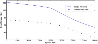
Figure 8. Continuous performance comparison between hairpin and stranded machines.
Assessing the trade-offs between hairpin and stranded windings is a complex multiphysics challenge, that involves detailed electromagnetic analyses and thermal simulations. Ansys tools empower you to understand these complexities and make data-driven design decisions during the development process.
Ansys Motor-CAD automatically computes feasible wave patterns for the hairpin windings. This feature helps in choosing the proper number of slots and layers combinations in the early design stage. Ansys Maxwell is capable of complex FEA simulation and couples the FE models to the external circuit to verify the possible presence of circulating currents.
Finally, Motor-CAD couples electromagnetic analysis to the thermal model compute machine performance while considering the cooling system. This can be done in the early design stage and during optimization processes to evaluate thermal performance of different winding solutions. Request your 30-day free trial of Ansys Motor-CAD and you’ll have access to all the multiphysics tools needed to test your next hairpin winding motor design.