-
-
Software gratuito per studenti
Ansys potenzia la nuova generazione di ingegneri
Gli studenti hanno accesso gratuito a software di simulazione di livello mondiale.
-
Connettiti subito con Ansys!
Progetta il tuo futuro
Connettiti a Ansys per scoprire come la simulazione può potenziare la tua prossima innovazione.
Paesi e regioni
Customer Center
Supporto
Partner Community
Contatta l'ufficio vendite
Per Stati Uniti e Canada
Accedi
Prove Gratuite
Prodotti & Servizi
Scopri
Chi Siamo
Back
Prodotti & Servizi
Back
Scopri
Ansys potenzia la nuova generazione di ingegneri
Gli studenti hanno accesso gratuito a software di simulazione di livello mondiale.
Back
Chi Siamo
Progetta il tuo futuro
Connettiti a Ansys per scoprire come la simulazione può potenziare la tua prossima innovazione.
Customer Center
Supporto
Partner Community
Contatta l'ufficio vendite
Per Stati Uniti e Canada
Accedi
Prove Gratuite
ANSYS BLOG
June 7, 2022
EMA3D Cable vs. EMA3D Charge: High Voltage and Heavy Industry Applications
Electromagnetic simulation typically focuses on problems associated with electronics at either the chip or system level. Unanticipated engineering problems associated with electromagnetism, however, long predate modern electronics.
The first electrical transmission systems for communication were created in the 1870s, followed shortly by power distribution systems in the 1880s. These systems crisscross continents and enable contemporary civilization. Despite the maturity of electrical transmission and power distribution technologies, they are not without potential electromagnetic hazards.
For example, railroad tracks and power lines often run along the same corridors for long distances, especially in urban environments where they frequently share municipal zoning-mandated areas. To aggravate the matter, rail lines themselves are progressively being electrified, and some rail systems natively carry voltages for high-speed travel. Furthermore, the increasing prevalence of electronics on the trains — including cabin electronics — and electronics associated with signaling and traffic monitoring equipment presents another source of potential charge accumulation and hazardous discharge problems.
The railroad industry is developing its own protective devices to safeguard the electronics it deploys to manage train activity. One of these protective devices is the lightning arrestor, which protects rail equipment from lightning strikes on the rails themselves. These devices, however, have their limitations; they can withstand the high energies of lightning currents, which only last microseconds, but are not designed for longer-term events.
A more chronic problem than the occasional direct lightning attachment is the electromagnetic interference (EMI) between power and transmission lines and nearby rails. It’s common to see electrical lines running parallel to railroad tracks for miles, especially along urban corridors reserved for infrastructure. The time-varying currents found in electrical lines during normal operation can couple to nearby rails or equipment and induce currents and voltages on them. This problem is more severe when the rails and transmission lines parallel one another in proximity for a long distance and when the transmission lines are carrying large currents.
Rails are not, however, assembled as an uninterrupted line. They are instead constructed as adjoining segments with insulating joints between them. These insulating joints enable monitoring and signaling at designated locations. When a current is induced on a rail line due to nearby power lines, the insulating joints become voltage sources that can negatively affect signaling and monitoring stations.
Industry standards require these voltages be kept low. Low voltages prevent damage to equipment and injury to personnel, and they also degrade the insulating joints more slowly over time. The less degradation of the insulating joints that occurs, the greater the signaling reliability.
Though not part of normal operation, transmission line faults can also occur. A direct short to ground can cause up to 30,000 ampere current flows for as much as a full minute and result in high voltages near and on the rails.
Overcoming Electromagnetic Challenges
The above problems are quite challenging from the viewpoint of computational electromagnetics, particularly because of the size of the model that must be simulated (recall that rails and electrical lines may run parallel for miles). At the same time, the model must simulate small-scale physical areas such as insulating joints. The presence of rail depots with multiple tracks, complex electrical line routings, lines changing from above ground to below ground, and spacing changes between conductive paths all add to modeling difficulties. Electromagnetic simulation software meshing techniques and run times can become overburdened by such conditions.
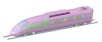
The variety of scenarios for rail and electric line EM interactions is quite surprising. Pictured below is a commuter rail environment common to European urban areas, with a pantograph on a rail car sliding along a catenary conductor (Figure 1). The interference and coupling responses are diverse and significant in this application.
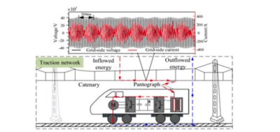
Figure 1. Commuter rail environment
The risks inherent to rail and electrical line interactions do not confine themselves to the electronic systems and equipment already discussed. High-speed electric multiple unit (EMU) trains generate high-frequency electric fields, low-frequency magnetic fields, and high-frequency wideband EM emissions during operation. Potential human health concerns arise because the EM disturbances are transmitted into the train car body from windows. These disturbances can affect passengers and train staff (see Figure 2). Therefore, there is increasing demand to simulate transmission volume, amplitude distribution characteristics, and exposure level of EM field emission for humans.
Figure 2: Disturbances can affect passengers and train staff.
All the problems discussed previously (and other application examples) are examined in an on-demand webinar. We also distinguish between the two solvers and describe how they can be used synergistically to model and simulate high voltage and heavy industry electromagnetic environments. Register today for Ansys EMA3D Cable vs. Ansys EMA3D Charge: Electromagnetic Hazards on Rail Assets.