Synopsys and Ansys power the future of innovation—connecting silicon to systems.
-
-
Software gratuito per studenti
Ansys potenzia la nuova generazione di ingegneri
Gli studenti hanno accesso gratuito a software di simulazione di livello mondiale.
-
Connettiti subito con Ansys!
Progetta il tuo futuro
Connettiti a Ansys per scoprire come la simulazione può potenziare la tua prossima innovazione.
Customer Center
Supporto
Partner Community
Contatta l'ufficio vendite
Per Stati Uniti e Canada
Accedi
Prove Gratuite
Prodotti & Servizi
Scopri
Chi Siamo
Back
Prodotti & Servizi
Back
Scopri
Ansys potenzia la nuova generazione di ingegneri
Gli studenti hanno accesso gratuito a software di simulazione di livello mondiale.
Back
Chi Siamo
Progetta il tuo futuro
Connettiti a Ansys per scoprire come la simulazione può potenziare la tua prossima innovazione.
Customer Center
Supporto
Partner Community
Contatta l'ufficio vendite
Per Stati Uniti e Canada
Accedi
Prove Gratuite
Ansys Blog
April 28, 2020
How to Design and Understand Unusual Tensegrity Structures
The videos that engineers love to share with each other tend to depict non-intuitive and fascinating physical systems. A recent favorite is The Action Lab’s floating table which demonstrates the unusual nature of tensegrity structures.
How does The Acton Lab’s floating table work?
Tensegrity, or tensile integrity, describes a system of isolated, compressed components within a network of chords that are under continuous tension. In a pure tensegrity structure, these components do not touch but experience compression nonetheless.
It’s hard to believe that strings could be made to support compressive loads. We can imagine it suspending a load using its tensile strength — like your classic crane. But chords aren’t able to support compression on their own. However, with the right setup and balancing, they can suspend a system of components that are under compression.

The chord in a crane is a classic system
under tension. It is not able to support
compressive loads on its own but that
changes with the right tensegrity setup.
A structure that experiences this form of floating compression gains strength from the chords under tension which suspend the compressed components. As a result, these systems give chords the ability to support a system under compression.
How Does Tensegrity Work?
Though a crane can’t support compressive loads on its own, it can be the secret to building a tensegrity structure.
A simulation of the floating table
For instance, in the floating table example, the two pieces of plastic that make up the base and top contain a crane-like structure. These structures are held together through the tension of the middle string. The three strings added to each corner of the base and top sections are there to add stability.
It’s all about balancing weight. The chord attached to the crane-like beams can only hold weight in one direction. In a perfect world, the only force acting on the system would be gravity and the system would be balanced in a way that this middle string would be all that is needed.
But in reality, only having one string would create an unstable system — like a pendulum. The other strings add stability by altering their tension in accordance with the weight distribution.
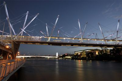
The Kurilpa Bridge (originally the Tank Street Bridge) over the
Brisbane River in Brisbane, Queensland, Australia
These suspension structures have practical applications for bridge construction. For example, the Kurilpa Bridge in Brisbane, Queensland, Australia, is one of the most famous hybrid tensegrity structures that people can use to traverse over a waterway. Its suspended by a series of crane-like pillars that use chords to hold the structure in place.
However, like the floating table, it could be hard to comprehend how this structure remains intact. To get a better idea, engineers can build a model of the bridge, or the floating table, using string and 3D printed parts. For those without access to a 3D printer, they can try building the suspended components out of Lego or Popsicle sticks.
How to Design and Simulate Tensegrity Structures
To learn how to design and model these structures, it’s great to start with a simple example — like the floating table.
Simulation of the floating table shows how some plastic
beams are in compression and some are in tension.
The majority of the force is on the middle string
To simplify computations, engineers will have to find ways to reduce the complexity of the model. In this case, the base, crane-like structures and chords can all be modeled as surfaces, beams and strings respectively. As a result, there is no need for solid modeling.
Cable element functionality was recently added in Ansys Mechanical 2020 R1. This is an upgrade to previous link elements.
These cable elements only work with tension and their ends are free to rotate. This differs from a beam element which can experience tension, compression and is welded into place.
Once the simulation is created, engineers can use it to optimize the placement of the cables to better distribute the weight, account for natural frequencies and stabilize the structure. They can also run a buckling simulation if they are concerned that one of the suspended elements might buckle, or break, if one of the cables were to fail.
If this simulation concept were to be expanded to a bridge design, the engineers would also need to optimize it for variable weight distributions, strong winds, earthquakes and other conditions. These simulations can be used to ensure that the base, crane-like structures and cables will all be able to survive the forces they would experience in the field.
As a result, engineers can find the Achilles heel of their design and focus their optimizations until they are sure the structure will survive in the real world. Generally, this optimization will consist of changing the geometry, cross section, materials and placements of the suspended objects and chords.
To learn more about the new features in Ansys Mechanical, watch the webinar: Ansys Mechanical 2023 R1 Update.
Any and all ANSYS, Inc. brand, product, service and feature names, logos and slogans such as Ansys and Ansys Mechanical are registered trademarks or trademarks of ANSYS, Inc. or its subsidiaries in the United States or other countries.