-
-
Software gratuito per studenti
Ansys potenzia la nuova generazione di ingegneri
Gli studenti hanno accesso gratuito a software di simulazione di livello mondiale.
-
Connettiti subito con Ansys!
Progetta il tuo futuro
Connettiti a Ansys per scoprire come la simulazione può potenziare la tua prossima innovazione.
Customer Center
Supporto
Partner Community
Contatta l'ufficio vendite
Per Stati Uniti e Canada
Accedi
Prove Gratuite
Prodotti & Servizi
Scopri
Chi Siamo
Back
Prodotti & Servizi
Back
Scopri
Ansys potenzia la nuova generazione di ingegneri
Gli studenti hanno accesso gratuito a software di simulazione di livello mondiale.
Back
Chi Siamo
Progetta il tuo futuro
Connettiti a Ansys per scoprire come la simulazione può potenziare la tua prossima innovazione.
Customer Center
Supporto
Partner Community
Contatta l'ufficio vendite
Per Stati Uniti e Canada
Accedi
Prove Gratuite
ANSYS BLOG
October 11, 2021
Combustor Turbine Interaction Challenges and Solutions
Whether it is for engine development or technology maturation, the focus of gas turbine manufacturers varies from module to module, but ultimately coalesces to four competing technology areas:
- Meet emissions, noise, and safety regulatory requirements
- Build an efficient engine
- Exceed durability requirements
- Overcome weight or specific fuel consumption constraints
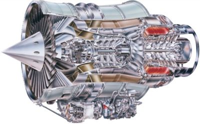
Honeywell turbofan engine
In the last few decades, improving engine efficiency in the Brayton cycle has become possible by focusing on a few levers such as increasing the overall pressure ratio, increasing turbine inlet temperature, using advanced materials, and reducing core engine size. These improvements have resulted in the emergence of compact aeroengines with tight and complex interactions between all modules.
These technological achievements were accomplished by honing in on the performance of each module — fan, compressor, combustor, and turbine — and how they come together as a remarkable machine. Design by analysis and validation by test has made this journey possible and faster.
Because design groups at OEMs are siloed, simulating each module of the gas turbine separately is still common practice. Modeling the interaction between these modules remains complex. In fact, the compact nature of the engine core makes it difficult to identify a clear interface location between components. In the hot section, the combustor and high-pressure turbine (HPT) are usually modeled separately with boundary conditions transferred to the turbine inlet. This approach is not ideal for capturing all the intricate flow details that travel between the combustor and the turbine and for tracking hot streak migration that determines turbine durability. Modeling combustor-turbine interaction requires a practical methodology that can be leveraged during the engine design process while ensuring accurate, fast, and robust CFD solutions.
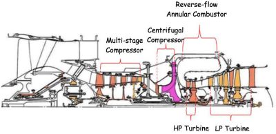
Turbofan engine schematic
Modeling Static Components in Combustor-Turbine Interaction
The first step to model combustor-turbine interaction is to start with the static components. Two modeling approaches were considered for the simulations shown in this blog. The first method — co-simulation — solves for the two components independently and transfers 2D profiles from the combustor exit to the stator inlet. Differing from traditional one-way transfer methods, a two-way coupling method was used that resulted in a feedback loop of profile exchanges until convergence of each component was reached. The second method — joint simulation — solves for the combustor and stator in the same computational domain.
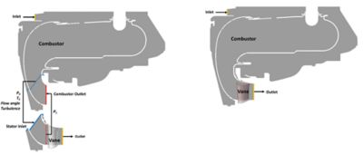
Co-simulation domains (left) and joint simulation domain (right)
The co-simulation approach comes with the challenge of finding adequate interface locations that define the combustor exit and vane inlet. The compact nature of the engine compounded with the presence of cooling channels and bleed outlets makes it difficult to define the overlapping region between the combustor domain and stator vane domain. The co-simulation approach also adheres to current modeling practices where the combustor is solved with scale resolving simulations, such as large eddy simulation (LES) or stress-blended eddy simulation (SBES), while the turbine is modeled with Reynolds-averaged Navier-Stokes (RANS). Statistically averaged quantities such as total pressure, total temperature, and velocity components are interpolated inside the combustor and applied to the stator vane inlet as boundary conditions. Careful attention is paid to accurately extracting turbulence quantities such as turbulence intensity and length scale from the combustor LES runs, because these parameters are known to have a big impact on mixing and heat transfer in the turbine.
The joint simulation approach is more straightforward with a single computational domain where scale resolving simulation and reacting flow prevail throughout the model. The mesh is refined to smoothly transition from combustor to vane requirements especially near the walls.
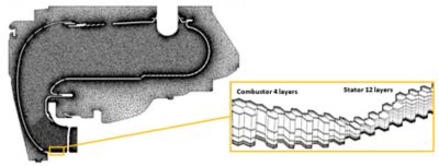
Joint simulation mesh and boundary layer transition.
The co-simulation approach requires at least one feedback loop to reach convergence in the combustor and vane doublet. Meaning that boundary condition profiles and performance parameters in both components — combustor temperature exit profile, total pressure drop, turbine inlet pressure — stabilize within a given threshold after two combustor simulations and two stator vane runs. In contrast, the joint simulation requires only a single run, thus having the advantage of requiring 50% less time than the co-simulation.
Temperature contours on mid-pitch and on vane doublet walls.
An important aspect of the joint-simulation and co-simulation comparison is to understand the impact of each method on the temperature distribution and vane wall thermal loading. The circumferantially averaged temperature distribution upstream of the vane leading edge shows little difference between the two methods. However, downstream of the trailing edge, the variations are more pronounced especially at the hub and shroud. The near wall temperature contours on the vane doublet are similar in the joint and co-simulations while both exhibit different radial gradients in each vane of the doublet.
Vane doublet mid-span hot streak migration.
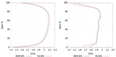
Average temperature profiles upstream and downstream of vane
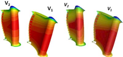
Near wall temperature contours on vane doublet walls.
When the coupling is limited to static components, the joint simulation is more practical process-wise and more efficient compute timewise while providing similar accuracy as the co-simulation in predicting combustor-stator interaction.
Rotor Simulations Raise Questions
As we include the rotor in the joint and co-simulations, the modeling conditions change. The co-simulation still requires at least one feedback loop between the combustor model and the stator-rotor model. However, the joint simulation time scale changes to adjust the rotor’s blade passing frequency with a time step that is one order of magnitude smaller than the combustor’s time step. The joint simulation now requires a significantly larger turnaround time to complete scale resolving simulation from combustor inlet to turbine exit.
The question becomes: Do the benefits of running joint simulation in terms of combustor turbine two-way interaction outweigh the long time it takes to obtain a solution? This will be the subject of our follow-on article.
Hot streak migration through the high-pressure turbine.