-
-
Software gratuito per studenti
Ansys potenzia la nuova generazione di ingegneri
Gli studenti hanno accesso gratuito a software di simulazione di livello mondiale.
-
Connettiti subito con Ansys!
Progetta il tuo futuro
Connettiti a Ansys per scoprire come la simulazione può potenziare la tua prossima innovazione.
Customer Center
Supporto
Partner Community
Contatta l'ufficio vendite
Per Stati Uniti e Canada
Accedi
Prove Gratuite
Prodotti & Servizi
Scopri
Chi Siamo
Back
Prodotti & Servizi
Back
Scopri
Ansys potenzia la nuova generazione di ingegneri
Gli studenti hanno accesso gratuito a software di simulazione di livello mondiale.
Back
Chi Siamo
Progetta il tuo futuro
Connettiti a Ansys per scoprire come la simulazione può potenziare la tua prossima innovazione.
Customer Center
Supporto
Partner Community
Contatta l'ufficio vendite
Per Stati Uniti e Canada
Accedi
Prove Gratuite
ANSYS BLOG
October 10, 2022
Ansys and EMA Help Intel Achieve the Impossible: EMI Simulation of an Entire Server
Electromagnetic interference (EMI) has always been a challenge for developers of electronic products, but it’s getting increasingly more difficult as semiconductor geometries shrink to 5nm and less as components are crammed closer together and clock cycle speeds decrease. A further obstacle results as companies push to eliminate most prototyping steps and achieve first-time success right off the factory line.
Solving these challenges is especially important for a company like Intel, a leader in computer technology, who can’t be delayed by EMI challenges. So, in 2020 they set a goal of simulating the electromagnetic properties of an entire server simultaneously, and they put principal engineer, Michael Leddige, and signal integrity engineer, Cesar Mendez-Ruiz, in charge of the project.
“Unlike signal integrity, where you can chop your problem into small pieces and analyze them and then paste all the pieces back together, EMI is by essence a system-level problem,” says Mendez-Ruiz. “Because it can be caused by anything — the silicon circuitry inside the integrated circuit, which is something that happens at the nanometer level; the package or the heat sink; or something bigger like a poorly designed voltage in the circuit that injects all its energy into the power plane and then radiates it everywhere.”
Putting Simulation to the Test
Simulating a tablet or a laptop would be challenging enough, but Intel deals with huge servers, as much as 4 standard units (4U) high, containing multiple processors, memory, cables, and numerous other components — not to mention the metallic package around the server — that can cause EMI problems.
Mendez-Ruiz had previous success with both Ansys HFSS and Ansys SIwave, but felt the extreme challenge of tackling the full server EMI simulation required additional direct support. He called in Ansys engineering, defined the full scope of the problem, and asked for some help.
Around this time, he saw an advertisement for EMA, whose electromagnetic simulation software was sold exclusively through Ansys. He contacted Ansys for an evaluation license and liked the results. Soon Intel, Ansys, and EMA engineers were working together to improve the interoperability of Ansys EMA3D Cable with HFSS and SIwave.
A List of Requests
To delineate the parameters of the project, Intel developed a list of requirements for the interoperability and functionality of HFSS, SIwave, and EMA3D Cable software:
- EMA3D Cable should be able to import solved fields from SIwave and HFSS for Intel’s electronic device sub-components. Once the fields were imported, Intel needed the ability to rotate and translate the position of the sub-components within the enclosure.
- Intel often used EMI absorbing tapes, so EMA3D Cable must have an ability to simulate thin, magnetically lossy materials.
- Intel needed EMA3D Cable to have a sub-grid capability to increase the resolution of key parts of the simulation geometry.
- EMA3D Cable is a time-domain simulation product. However, Intel needed the capability to simulate frequency-dependent materials.
Results of the Project
Ultimately, Ansys and EMA met all the requirements and delivered software enhancements to support the simulation effort. It would take too long to describe all the enhancements in detail, so we’ll just report on a few of the results of the joint effort.
HFSS Field Import into EMA3D Cable
Initially, for six PCIE modules in a server working in parallel, Intel would have to run HFSS six separate times with the module in each of the six positions in the server so that when the data was transferred to EMA3D Cable it would be placed in the right location.
“I needed to wait for one week for one simulation and I needed to run it six times,” says Mendez-Ruiz. “The new software lets me apply linear transformations to the sensors to position them in the correct way so I don’t have to simulate the same thing six times.”
SIwave Field Import into EMA3D Cable
SIwave is traditionally used for simulating the electromagnetic near-field from printed circuit boards (PCBs) and packages. Now, Intel can export that data with one click to EMA3D Cable. This is a great improvement in the simulation workflow.
Meshing the complex geometry of an entire server presents several challenges and can be time-consuming. But EMA3D Cable uses a voxel grid mesh instead of the traditional tetrahedra used by the finite element method, resulting in a forgiving mesh that can be completed much faster than before. This almost instant meshing saves Intel simulation preparation time.
Rapid and Accurate Modeling of Cables
Perhaps the greatest improvement Intel saw from incorporating EMA3D Cable into their workflow was the simulation of the cables that connect PCBs. Previously, engineers had to model every geometric feature of the cable, which is difficult because they involve wires less than a millimeter in diameter that are braided together in complex, twisting configurations. These braids, or weaves, greatly affect the electromagnetic coupling.
EMA3D Cable combines two solvers: the solver for the 3D structure that uses the voxel grid mesh, and a solver based on multi-conductor transmission line theory for the cables. The models for the shields, the foils, and the cables are all handled through the cross section. In the simulation, when you see the cable, you're seeing the 2D cross section just as if you just took a cable and cut it with scissors. The third dimension — the path of the cable — lives in the 3D geometry. Essentially, a one-dimensional line shows where the cable goes and the 2D cross section reveals what's inside that one-dimensional line.
“The EMA3D tool handles the cabling like an independent simulation from the voxel grid meshing of the rest of the computer,” says Mendez-Ruiz. “It doesn’t have to mesh the cables initially, but in the end it combines the voxel mesh with the 2D representation of the cables to come up with solution in a way that couldn’t be done before.”
With this unique, two-part simulation method, Intel can simulate an entire server in hours or days, instead of what in the past might have taken months or maybe years to prepare as an analyst.
“Part of the challenge was to account for different scenarios — not only the twisting of cables inside a server but also different termination options,” says Mendez-Ruiz. “You don’t always terminate with only one resistor or one linear component. You can have different termination scenarios. You can also have some shielding from an open circuit, which can have huge implications on the performance of the compute system. EMA has made some significant improvements in this area during this project.”
EMA3D Subgrid Meshing
Another big challenge was to develop a subdomain inside the global domain of the model. Intel wanted to mesh the subdomain with a finer grid to get more simulation detail in places where that was important.
For example, on a PCIE model, a heat sink is constructed from thin laminations of stainless steel, which requires a very small grid size to correctly mesh this subdomain. Without a subdomain, an engineer would have to apply this small mesh size to the entire server, including areas that do not need such detailed simulation. The simulation would take longer to run because of wasted precision in areas that don’t require it.
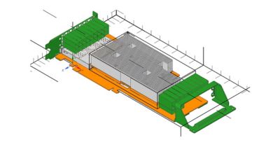
PCIE module (top cover not shown) with sub-grid defined in heat sink area for smaller cell size only in this region
“Without a subdomain, I pay a huge time penalty on the outside portion of the server,” says Mendez-Ruiz. “It’s not practical to simulate a complete server if you have to live with the penalty. So, we requested an option to make a subdomain with a very fine cell size, existing alongside a global domain with a coarser mesh that would do a good job in meshing the rest of the server. This was one of the main developments from Ansys that will make it possible to simulate an entire server.”
The Future of the Project
Ansys has delivered on all of Intel’s requests and continues to work with them as they work toward putting all these enhancements together to simulate an entire server.
“We are currently in a good state in terms of the maturity of the simulation tools, but we are now trying to develop our internal methodology,” says Mendez-Ruiz. “The tool is there, but how do you use it? How do you set it up so you can replicate and correlate with measurements you make in the lab?"
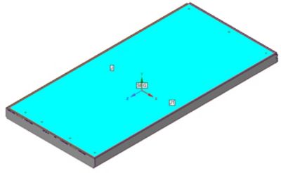
Full 1U chassis shielding effectiveness evaluation setup exploiting the seam/joint capability to account for EM leakage through assembly gaps, using a harness as a monopole antenna source and a field probe 0.5m apart from front panel.
He says he will consider the project to be finished when the simulation software catches a problem in the design stage and solves it before they see it in the lab. That is what complete success looks like to Mendez-Ruiz. He is confident that by the end of this year, he will be able to predictively model a full system to eliminate potential EMI problems before they can occur, thanks to a lot of hard work from Intel, Ansys, and EMA.
“The impact of this joint program on Intel has been that we went from not being able to even consider simulating a whole server to now having something that is doable,” says Mendez-Ruiz. “It was a three-way effort and that’s what makes this story so compelling. Intel, Ansys, and EMA invested whatever effort was necessary to make it happen. It’s a big win for all of us.”
Intel, the Intel logo, and other Intel marks are trademarks of Intel Corporation or its subsidiaries.