-
-
Software gratuito per studenti
Ansys potenzia la nuova generazione di ingegneri
Gli studenti hanno accesso gratuito a software di simulazione di livello mondiale.
-
Connettiti subito con Ansys!
Progetta il tuo futuro
Connettiti a Ansys per scoprire come la simulazione può potenziare la tua prossima innovazione.
Customer Center
Supporto
Partner Community
Contatta l'ufficio vendite
Per Stati Uniti e Canada
Accedi
Prove Gratuite
Prodotti & Servizi
Scopri
Chi Siamo
Back
Prodotti & Servizi
Back
Scopri
Ansys potenzia la nuova generazione di ingegneri
Gli studenti hanno accesso gratuito a software di simulazione di livello mondiale.
Back
Chi Siamo
Progetta il tuo futuro
Connettiti a Ansys per scoprire come la simulazione può potenziare la tua prossima innovazione.
Customer Center
Supporto
Partner Community
Contatta l'ufficio vendite
Per Stati Uniti e Canada
Accedi
Prove Gratuite
ANSYS BLOG
February 4, 2022
All Wound Up: New Litz Wire Modeling and Loss Prediction in Ansys Maxwell
For electromagnetic (EM) designers and engineers, delivering future power applications for disruptive end-product technologies means overcoming enormous challenges and demands. Increasing power density and efficiency in a smaller, lighter-weight device is a steep enough climb. Add in requirements to reduce manufacturing costs, make the design reusable, ensure high thermal reliability, and be first to market, and the summit can seem pretty far away — if not entirely unreachable.
Ansys Maxwell, the gold standard 2D/3D finite element (FE) EM field solver for low-frequency applications, helps bring this monumental task down to size. That includes predicting EM losses through advanced material modeling capabilities — a key factor in designing peak performance into electric motors, electronic transformers, magnetic inductors, and other EM power devices.
Maxwell enables EM designers and engineers to:
- Validate different concept designs for performance parameters
- Ensure design efficiency in the operating regions
- Evaluate the best design using advanced optimization algorithms
- Scale simulations via high-performance computing (HPC)
- Satisfy safety objectives using reduced-order models for more complete drive analysis
Which Loss is Which?
To calculate the efficiency and ensure high thermal reliability of electric machines, transformers, and other electrical equipment, engineers need to understand the source of EM losses before they can predict the heat they generate. Without this knowledge, it’s difficult to build appropriate and effective thermal management into a design because it takes more correlations between measurements and simulation to calibrate the virtual model. This introduces more iterations within the design process, increasing time to market.
Of particular interest is the heat from copper loss in Litz wire windings.
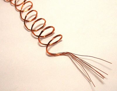
Figure 1: Litz wire can contain hundreds to thousands of individually insulated strands of copper wire.
Litz wire is composed of hundreds to thousands of individually insulated strands of copper wire, connected electronically, and twisted or braided together in a uniform pattern.
Litz wire windings are used extensively for high-frequency (up to 1 MHz) magnetic components to reduce alternating current (AC) losses as operating frequencies increase.
Increased frequency impedes AC from passing through the conductor, resulting in EM loss from skin and proximity effects. By simultaneously distributing the electrical current among its independent strands, Litz windings reduce the eddy current losses that originate from skin and proximity effects while also lowering operating temperature. As more high-power designs involve replacing fewer solid conductors with multiple conductors composed of Litz wires, accurately predicting winding losses has become extremely important. With its new Litz wire modeling capabilities, Ansys Maxwell 2022 R1, available via the Ansys Customer Portal, can now predict EM losses on copper wire strand configurations with temperature feedback.
More Efficient Simulation
The very thing that gives Litz windings their advantage — reducing AC losses by enabling electrical currents to pass through various filaments or strand topologies organized in a single structure — makes them more susceptible to mechanical effects.
To make the winding configuration robust and reliable —and to ensure device EM performance sustains mechanical integrity — designers must understand how the winding configuration will affect the operating condition of a particular design. This includes knowing how much electric current the configuration can carry, how much heat will occur as a result, and how this heat will impact the electric current’s flow. Not only does this information help predict device performance and trim total research and development time, but it also reduces collateral costs to the overall design. In the long run, that means a positive return on investment (ROI).
However, because a Litz wire bundle can contain thousands of small strands, it is difficult (or even impossible) to model every strand explicitly using finite elements. It is possible to model a Litz bundle by representing each physical (or constitutive) wire as a solid conductor, but the FE simulation pain point is the mesh required to capture the AC losses on each solid wire.
Using the Litz wire modeling capabilities within Maxwell overcomes that hurdle.
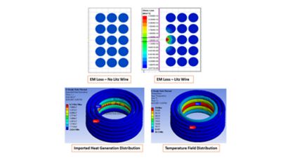
Figure 2: Ansys Maxwell Litz wire loss prediction simulation with temperature feedback.
Maxwell provides an accurate representation of the conductive region accounting for the AC effects that cause losses. This significantly reduces the number of finite elements and design unknowns, vastly improving simulation efficiency.
- Maxwell generates different types of Litz wire topologies, including round, square, or rectangular cross sections during design setting.
- It discretizes the geometry and creates an equivalent stranded model used in frequency- and time-domain finite element analysis (FEA).
- Electromagnetic losses are computed and mapped into a thermal design for temperature rise calculations, in which the 3D geometry and material assignment are shared between electromagnetic and thermal modules.
- The Litz wire temperature is mapped back to Maxwell for a new electromagnetic simulation, and Litz wire EM loss due to updated electric conductivity is computed.
Automated Open-Loop Power Design
With Ansys 2022 R1, Maxwell also employs system pushback excitation for 2D/3D magnetic transient, enabling an automated open-loop FEA power design with decoupled circuit/system input. This provides solutions an order of magnitude faster compared to closed-loop analysis.
A typical electric drive system consists of a source of energy components (e.g., a battery or electric grid); power distribution components (such as cables or busbars); power conversion components (inverters and converters); electromagnetic components (electrical machines, magnetic actuators, electronic transformers, power transformers); and a control system to regulate the entire operation.
In these topologies, EM component operation is driven by the energy transferred from the source to its terminals (windings). The interaction of the EM component with other drive system components — e.g., with the inverter through its switching frequency — affects its performance. To understand the operating conditions and losses of the EM component requires detailed FEA with realistic excitations and an accurate representation of the form of energy transferred to the terminals.
The most detailed information comes from applying a closed-loop analysis, in which the energy in the system is balanced based on the feedback that regulates the operation of the system. Today, this can be done as a co-simulation between the circuit design in Ansys Twin Builder — which enables engineers to create a simulation-based digital twin — and the FEA design in Maxwell. However, this requires considerable computational time. Additionally, as the system/circuit configuration and geometries of the EM components become more complex, computational complexity also increases — meaning time to solution takes even longer.
As an alternative, performing an open-loop analysis through a pushback excitation from a circuit/system simulation in Twin Builder to Maxwell transient analysis provides designers with the answers they need in a fraction of the time. That’s because system/circuit run time and the data exchange between the FEA and circuit solvers are not considered in this approach.
By measuring any transient waveform throughout the circuit/system topology, Twin Builder can automatically assign excitation conditions on a Maxwell transient design. Using that waveform as winding excitation, Maxwell can then perform time-stepping analysis on 2D or 3D designs.
One of the major advantages of using pushback excitation in Maxwell is use of time-domain method (TDM) as HPC to speed up the FEA solution.
Predicting Accurate Winding Losses in Power Applications with Ansys Maxwell
Seamless Compatibility
In addition to Twin Builder, Maxwell integrates seamlessly with other Ansys products to improve the overall design workflow.
For example, using Maxwell with Ansys Motor-CAD helps optimize electrical machine design performance. Additionally, integrating the software with Ansys Mechanical, Ansys CFD solutions, Ansys Icepak, or Ansys optiSlang enables complex thermal and cooling management, noise-vibration-harshness analysis, and better design reliability studies.
Download the latest release of Ansys Maxwell to gain access to these powerful new capabilities, and don’t forget to sign up for our 2022 R1 Maxwell Webinar.