Synopsys and Ansys power the future of innovation—connecting silicon to systems.
-
-
Software gratuito per studenti
Ansys potenzia la nuova generazione di ingegneri
Gli studenti hanno accesso gratuito a software di simulazione di livello mondiale.
-
Connettiti subito con Ansys!
Progetta il tuo futuro
Connettiti a Ansys per scoprire come la simulazione può potenziare la tua prossima innovazione.
Customer Center
Supporto
Partner Community
Contatta l'ufficio vendite
Per Stati Uniti e Canada
Accedi
Prove Gratuite
Prodotti & Servizi
Scopri
Chi Siamo
Back
Prodotti & Servizi
Back
Scopri
Ansys potenzia la nuova generazione di ingegneri
Gli studenti hanno accesso gratuito a software di simulazione di livello mondiale.
Back
Chi Siamo
Progetta il tuo futuro
Connettiti a Ansys per scoprire come la simulazione può potenziare la tua prossima innovazione.
Customer Center
Supporto
Partner Community
Contatta l'ufficio vendite
Per Stati Uniti e Canada
Accedi
Prove Gratuite
ANSYS ADVANTAGE MAGAZINE
DATE: 2018
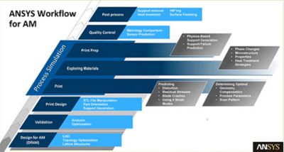
Including Simulation in the Additive Manufacturing Workflow
By Louise Geekie, Project Manager, Croft Filters, Ltd., Warrington, UK
When designing a new industrial filter, Croft Filters needed to overcome warping during the selective laser melting additive manufacturing process. By leveraging one of Ansys’s additive manufacturing simulation solutions, Additive Print, in their design-to-print workflow, engineers were able to quickly generate a printable design and avoid multiple build failures, thus reducing time to market and prototyping expenses by 50 percent.
To develop a new filter that would decrease the pumping energy required by the industrial end user, Croft engineers reasoned that aligning the holes with the flow would reduce the amount of pumping energy required to drive the fluid through them. This filter design required intricate internal contours that cannot practically be produced by traditional manufacturing methods, so Croft turned to metal additive manufacturing. The selective laser melting (SLM) additive manufacturing process employed produces parts by sequentially melting tiny areas of a powder bed with a moving laser.
As each melted section cools, it experiences compressive and tensile forces, but is constrained by its attachment to nearby solid areas. The resulting residual stresses may cause the part to warp. In the past, Croft engineers used trial-and-error methods to eliminate warpage or at least reduce it to the point that dimensional tolerances could be met. By using the Ansys Additive Print solution to guide their efforts in solving distortion problems, they have cut solution time in half and reduced prototyping expenses by about the same amount.
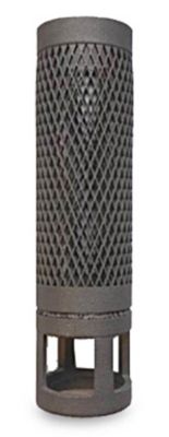
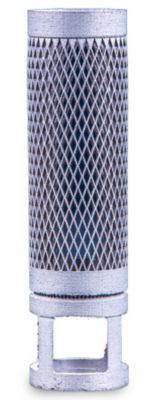
- First attempt to produce the part by additive manufacturing resulted in considerable distortion.
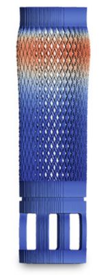
- ANSYS additive manufacturing simulation of the original design matched the distortion shown on the real part.
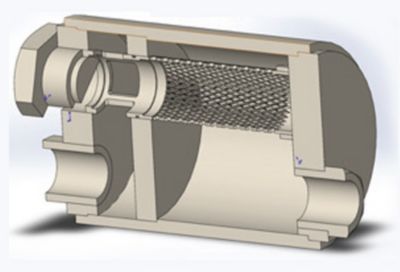
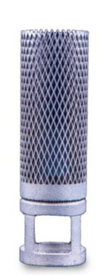
- Croft engineers first simulated then built a prototype (shown here) of the part with the top section removed to diagnose the problem.
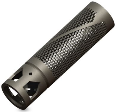
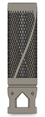
- CAD model of redesigned part with supports incorporated into mesh.
- A combination of supports and distortion compensation made it possible to eliminate the distortion problem.
FILTER BUILT BY SLM PROCESS
During the SLM process, a wiper pushes a thin layer of powdered metal (316L stainless steel, in this case) across a build plate, and a laser tracks across the layer to melt the areas of that layer that will form a cross section of the part. As each layer is completed, another layer of powder is applied to the partially built part, and the laser melts a new cross section. The cycle continues until the part is complete.
As each section of the part on the top layer cools, the solid underlying layers resist the thermal contractions, applying a tensile stress to the top layer. Likewise, the top layer applies compressive stresses to the solid area beneath it. The geometry of the part and auxiliary structures added to support overhangs and conduct heat have a major but difficult-to-predict effect on residual stresses. Areas that are relatively free to move have less residual stress, while areas restricted from moving have a higher level of residual stress. In this case, the finished part did not meet manufacturing tolerances because residual stresses generated several distortions in the x and y planes and elongation in the z plane.
In the past, Croft engineers would have relied on trial-and-error methods to determine what changes in the part orientation, support structures, machine parameters, material specifications and component design would enable them to meet manufacturing tolerances. It typically took four weeks to achieve a satisfactory part using this approach and consumed considerable resources, including engineering time, to generate new design iterations. It also took more build time on additive manufacturing systems and more powdered metal materials to produce additional prototypes.
"Croft Filters cut solution time in half and reduced prototyping expenses by about the same amount."
SIMULATION IS USED TO SOLVE ADDITIVE MANUFACTURING PROBLEMS
Simulation enabled the much faster and less-expensive approach that was used in this project. Croft engineers uploaded the original STL file into Additive Print. Additive Print provided graphical visualization of layer-by-layer stress accumulation and high-strain regions throughout the build. The software predicted distortion and residual stress of the as-built parts, including visualization of the differences between the original, undeformed geometry and the final deformed geometry, before and after removal from supports. These results provided diagnostic information that would not be possible otherwise. Also, the information was delivered in a small fraction of the time and cost that would have been required to build the part.
The simulation results revealed that the distortion was largely caused by the high-strength top section (a solid ring), which induced residual stresses in the weaker upper portion of the filtration mesh. The engineers tested this hypothesis by simulating the filter with and without the top section. Without the top section, the results showed zero distortion. Croft engineers built the topless part to confirm these findings, and the results matched the simulation. Even though the top ring was essential to maintaining the structural integrity of the part, the knowledge that it was responsible for the distortion during the manufacturing process provided valuable input to the design process.
Introducing the Most Powerful
Simulation Solution for Metal AM
MEETING THE DESIGN SPECIFICATIONS
Croft engineers tried adding supports to the filtration mesh. These supports were attached to the top ring to increase the strength of the mesh area in the top of the filter. They tried using two helical supports with geometry designed to avoid restricting flow while not adding too much material weight and build time. They also changed the shape of the inlets to pentagonal to increase the inlet area while keeping the holes self-supporting and reducing the amount of support material required. When they simulated the new design, the results showed that distortion was considerably reduced but was still not satisfactory for this product.
Engineers then leveraged the automatic compensation capability in Additive Print that adjusts the geometry of the build to compensate for the distortion. This feature moves the walls of the part in the opposite direction from that in which the distortion occurs to achieve the original design geometry. They simulated the distortion-compensated model and found that it overcompensated for the distortion, producing a small amount of distortion opposite to that found in the original geometry. So they used Additive Print to create a new geometry with the distortion compensation scaled to 0.75, 0.50 and 0.25 of the original amount. The simulation results for all these models still showed insufficient compensation for distortion. Finally, the engineers generated a model with distortion compensation scaled to 0.90. This design nearly eliminated distortion and met the design specifications.
Additive manufacturing allows companies to print parts that are impossible or very expensive to produce with traditional subtractive manufacturing methods. But organizations that are working to develop additive manufacturing into a real-world manufacturing process often must go through multiple trial-and-error processes to successfully generate high-fidelity parts. Simulation guides engineers to successfully create parts and processes at much lower cost and lead time than is required for trial and error. Croft engineers simulated the additive manufacturing process to determine the best part design and machine process parameters while minimizing the number of physical prototypes. The design of this part has been finalized, and it is moving to product launch.
Introduction to Ansys Additive Print Rapid Pre-Print Simulation for Metals