產品系列
查看所有產品Ansys致力於為當今的學生打下成功的基礎,通過向學生提供免費的模擬工程軟體。
Ansys Blog
April 2, 2020
Accelerated life testing (ALT) is an expedient and cost-effective solution to determine the reliability and robustness of an electronic product or component.
ALT uncovers potential failure risks and quantifies the life characteristics of a product or component at a much faster rate than in the field — leading to improved product design and faster time to market.
Product reliability is essential for success,
especially for electronic products
like printed circuit boards (PCB)
In order to increase stress and induce damage faster than in the field, ALT mimics environments that a product will likely encounter in the real world, such as:
To learn how to facilitate and implement these test protocols, watch the webinar: Test Plan Development – Acceleration Factors and Life Predictions.
An acceleration factor (AF) is the ratio of time-in-field to time-in-test for a particular failure mechanism and a key component when designing an effective ALT for determining life predictions.
AF: Acceleration Factor
Tfield: Time-in-field
Tt: Time-in-test
There are two types of ALT:
Engineers leverage qualitative ALT to reveal failure modes and mechanisms only. For example, qualitative tests include:
These are tests used to uncover common failure modes or design deficiencies that need to be worked on in order to improve the quality and reliability of the product. If the device survives, it passes the qualitative test. In addition, qualitative testing provides input for the types and levels of stress used in quantitative accelerated testing.
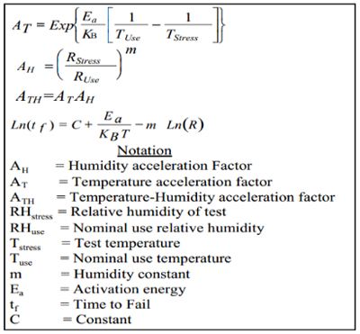
Quantitative ALT quantifies the life characteristics of the electronic component with some reliability and confidence levels. The use of an accelerated model correlates the applied stressors to the time to failure. For example, stress tests that are commonly used include:
Example of an accelerated
model for THB testing
In addition to ALT for field life predictions, specific board level reliability tests (BLRT) can be performed on printed circuit board assemblies (PCBA) to assess the robustness of the semiconductor packaging once the device is soldered to its printed circuit board (PCB). These can be qualitative or quantitative in nature, depending upon the specific test, and help to ensure a reliable assembly from the design and manufacturing process.
Acceleration in tests can take the form of:
Usage rate acceleration increases the rate of stress applied to a device under test (DUT) while keeping that stress equivalent to what it would experience in the field. If the increased frequency is within reason in test, no higher stressors will be applied to the DUT.
For example, engineers can test a microwave oven door by opening and closing it every 10 seconds until they reach a determined number of cycles expected in the field. This is a much faster rate than what would be expected even in a commercial setting, however, the forces applied in actuating the door are still the same as in the field. The relatively low duty cycle in the field compared to high frequency of cycling achieved in test allows one to complete the test in a matter of a few hours or days rather than years. If the DUT had a much higher duty cycle in the field (closer to continuous duty), the amount of acceleration achievable in test would be limited.
High stress acceleration increases the level of stress on a device beyond what it would encounter in the field. The term higher stress is used here because the term overstress can have connotations of exceeding the design limits of the device — which is not desirable. When using higher stress acceleration, it is not recommended to stress the device to the point where the test is inducing failure mechanisms that the device would not otherwise experience in the field.
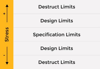
For example, operating an outdoor light switch under high and low temperatures in tests that exceed the worse-case temperature extremes — say conditions close to Phoenix, AZ — would be appropriate as long as the test temperatures remain within the design limits of the light switch. Thus, design limits must be considered based on the specification and material properties of the device to limit the stress level in test.
Stress levels in test should stay within the design
and material property upper and lower limits
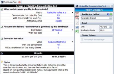
Once the ALT has been implemented with an AF, there are a number of parameters that can impact the test time for life prediction. These parameters include:
Parameters for life prediction setup
The AF is dependent upon the failure mechanism of interest (e.g., thermo-mechanical stress, thermal aging, etc.), which also drives the type of acceleration model used. The model should correlate to its corresponding parameters, such as activation energy, stress level, etc.
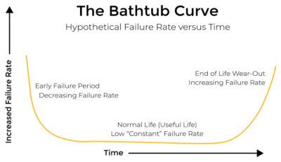
The bathtub curve
An adaptive and commonly used reliability distribution is the two-parameter Weibull with its associated beta value (β). This value can be based on failure history (calculated from a time- or cycles-to-failure plot) or an expected failure along the typical bathtub curve. Typically, β will be greater than one for wear-out type failure mechanisms:
With these parameters, a standard reliability software tool can be used to determine:
Once the test plan for the ALT has been determined and executed, the results can be analyzed. If there were no failures, the required reliability and confidence level metrics for the device and the failure mechanism(s) of interest have been determined. If there were failures, it is ideal to have several of them in order to better analyze the results statistically and extrapolate to an expected life. To learn more about acceleration factors (AF) and acceleration life testing ALT watch the webinar: Test Plan Development – Acceleration Factors and Life Predictions.
我們將在此解答您的問題,並期待與您交流互動。Ansys 的銷售團隊成員會立即與您聯絡。