-
-
학생용 무료 소프트웨어에 액세스하기
차세대 엔지니어에게 힘을 실어주는 Ansys
학생들은 세계적 수준의 시뮬레이션 소프트웨어를 무료로 이용할 수 있습니다.
-
지금 바로 Ansys에 연결하십시오!
미래를 설계하기
시뮬레이션이 다음 혁신을 어떻게 지원할 수 있는지 알아보려면 Ansys와 연결하십시오.
국가
무료 트라이얼
제품 및 서비스
학습하기
회사 정보
Back
제품 및 서비스
ANSYS BLOG
September 15, 2017
Topology Optimization of a Motorcycle Component
If you’re not familiar with topological or topology optimization, a simple description is that we are using the physics of the problem combined with the finite element computational method to decide what the optimal shape is for a given design space and set of loads and constraints. Typically our goal is to maximize stiffness while reducing weight. We may also be trying to keep maximum stress below a certain value. Frequencies can come into play as well by linking a modal analysis to a topology optimization.
Why is topology optimization important? First, it produces shapes which may be more optimal than we could determine by engineering intuition coupled with trial and error. Second, with the rise of additive manufacturing, it is now much easier and more practical to produce the often complex and organic looking shapes which come out of a topological optimization.
Ansys has really upped the game when it comes to utilizing topology optimization. Starting with version 18.0, topo opt is built in functionality within Ansys. If you already know Ansys Mechanical, you already know the tool that’s used. The Ansys capability uses the proven Ansys solvers, including HPC capability for efficient solves. Another huge plus is the fact that Ansys SpaceClaim is linked right in to the process, allowing us to much more easily make the optimized mesh shape produced by a topological optimization into a more CAD representation set for use in validation simulations, 3D printing, or traditional manufacturing.
The intent of this blog is to show the current process in Ansys 18.1 using a simple example of an idealized motorcycle front fork bracket optimization. We don’t claim to be experts on motorcycle design, but we do want to showcase what the technology can do with a simple example. We start with a ‘blob’ or envelope for the geometry of our design space, then perform an optimization based on an assumed set of loads the system will experience. Next we convert the optimized mesh information into solid geometry using Ansys SpaceClaim, and then perform a validation study on the optimized geometry.
Here we show our starting point — an idealized motorcycle fork with a fairly large blob of geometry. The intent is to let Ansys come up with an optimal shape for the bracket connecting the two sides of the fork.
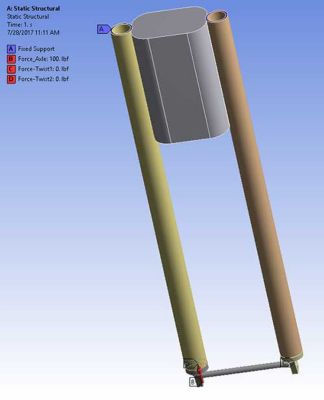
The first step of the simulation in this case is a traditional Static Structural simulation within Ansys Workbench. The starting point for the geometry was Ansys SpaceClaim, but the initial geometry could have come from any geometry source that Ansys can read in, meaning most CAD systems as well as Parasolid, SAT, and STEP neutral file formats.
A single set of loads can be used, or multiple load cases can be defined. That’s what we did here, to simulate various sets of loads that the fork assembly might experience during optimization. All or a portion of the load cases can be utilized in the topological optimization, and weighting factors can be used on each set of loads if needed.
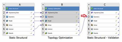
Here we see the workflow in the Ansys Workbench Project Schematic:
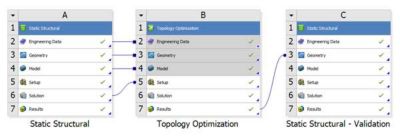
Block A is the standard static structural analysis on the original, starting geometry. This includes all load cases needed to describe the operating environment. Block B is the actual topological optimization. Block C is a validation study, performed on the optimized geometry. This step is needed to ensure that the optimized shape still meets our design intent.
Within the topology optimization, we set our objective. He we choose minimizing compliance, which is a standard terminology in topology optimization and we can think of it as the inverse which is maximizing stiffness.
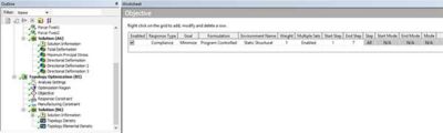
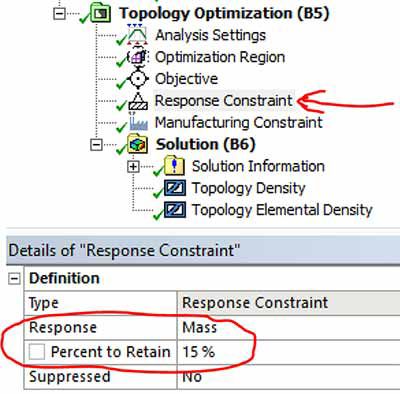
In the static structural analysis, 7 load cases were used to describe different loading situations on the motorcycle fork, and here all have been used in the optimization. Further, we defined a response constraint, which in this example is to reduce mass (actually retain 15% of the mass):
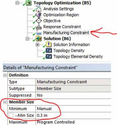
Another quantity that’s often useful to specify is a minimum member constraint. That will keep the topology optimization from making regions that are too small to 3D print or otherwise manufacture. Here we have specified a minimum member size of 0.3 inches:
Since the topological optimization solution uses the same Ansys solvers for the finite element solution as a normal solution, we can leverage high-performance computing (distributed solvers, typically) to speed up the solution process. Multiple iterations are needed to converge on the topology optimization, so realize that the topo opt process is going to be more computationally expensive than a normal solution.
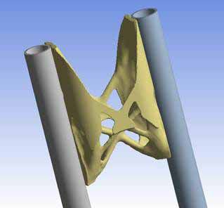
Once the optimization is complete, we can view the shape the topo opt method has obtained:
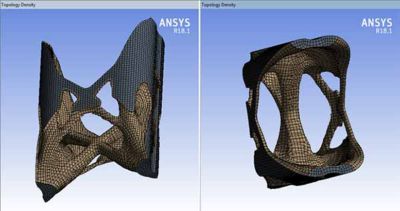
Notice that only a portion of the original model has been affected. Ansys allows us to specify which regions of the model are to be considered for optimization, and which are to be excluded.
Now that we have a shape that looks promising, we still need to perform a validation step, in which we rerun our static simulation with the loads and constraints we expect the fork assembly to experience. To do that, we really want a ‘CAD’ model of the optimized shape. The images shown above show the mesh information that results from the topo opt solution. What we need to do next is leverage the Ansys SpaceClaim geometry tool to create a solid model from the optimized shape.
A simple beauty in the Ansys process is that with just a couple of clicks we proceed from Block B to Block C in the Workbench project schematic, and can then work with the optimized shape in SpaceClaim.
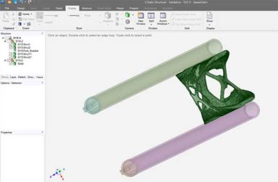
As you can see in the above image, SpaceClaim automatically has the original geometry as well as the new, optimized shape. We can do as much or as little to the optimized shape as we need, from smoothing and simplification to adding manufacturing features such as holes, bosses, etc. In this case we simply shrink wrapped it as-is.
Continuing with the validation step, the geometry from SpaceClaim automatically opens in the Mechanical window and we can then re-apply the needed loads and constraints and then solve to determine if the optimized shape truly meets our design objectives. If not, we can make some tweaks and run again.
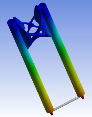
The above image shows a result plot from the validation step. The geometry efficiently comes through SpaceClaim from the optimization step to the validation step. The needed tools are all nicely contained within Ansys.
Hopefully this has given you an idea of what can be done with topology optimization in Ansys as well as how it’s done. Again, if you already know Ansys Mechanical, you already know the bulk of how to do this. If not, then perhaps what you have seen here will spark a craving to learn. We can’t wait to see what you create.
Learn more in our on-demand webinar: Structural Topology Optimization: What if Your Design Could Be Better